Val-Matic 3-24 Butterfly Valve User Manual
Page 5
5
INSTALLATION (Cont'd)
In all installations, the valve and adjacent piping
must be supported and aligned to prevent
cantilevered stresses on the valve. Lower valve into
line using slings or chains around the valve body.
Lubricate the flange bolts or studs and insert them
around the flange. Lightly turn bolts until gaps are
eliminated.
The torquing of the bolts should then be done in
graduated steps using the cross-over tightening
method. If leakage occurs, allow gaskets to absorb
fluid and check torque and leakage after 24 hours.
Do not exceed bolt rating or crush gasket more than
50 percent of its thickness; see tables below.
TABLE 2. MECHANICAL JOINT NUT TORQUES
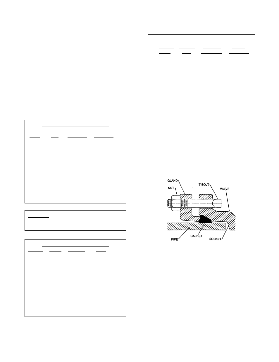
MECHANICAL JOINT ENDS: Clean ends of mating
pipe and valve sockets with soapy water (Figure 5).
Place lubricated gasket and retainer gland over pipe
end prior to installing valve. Install valve socket over
pipe. Press gland and gasket toward valve until
gasket is evenly set into valve socket.
FIGURE 5. MECHANICAL JOINT INSTALLATION
Insert T-bolts in valve flange and hand tighten nuts.
Torque nuts in four graduated steps using the cross-
over tightening method without exceeding the torque
listed in Table 2. Maintain an equal gap between
the gland and the face of the valve at all points
around the socket.
If a tight connection is not achieved, then the joint
should be disassembled, thoroughly cleaned, and
reassembled. Over-tightening, may cause damage
to the valve or gland.
MECHANICAL JOINT BOLT TORQUES
VALVE T-BOLT RECOM. MAX.
SIZE DIA TORQUE TORQUE
(in) (in) (ft-lbs) (ft-lbs)
4
3/4
75
90
6
3/4
75
90
8
3/4
75
90
10
3/4
75
90
12
3/4
75
90
14
3/4
75
90
16
3/4
75
90
18
3/4
75
90
20
3/4
75
90
150B FLANGE BOLT TORQUES
VALVE BOLT RECOM
MAX
SIZE DIA TORQUE
TORQUE
(in)
(in) (ft-lbs)
(ft-lbs)
3, 4 5/8 25
100
6
3/4 30
150
8
3/4 40
150
10
7/8 45
200
12
7/8 65
200
14
1 80
300
16
1 90
300
18
1 1/8 100
425
20
1 1/8 120
425
24
1 1/4 150
600
CAUTION: The use of raised-face flanges
or excessive bolt torque may
damage valve flanges.
250B FLANGE BOLT TORQUES
VALVE BOLT RECOM
MAX
SIZE DIA TORQUE
TORQUE
(in)
(in) (ft-lbs)
(ft-lbs)
4, 6
3/4 30
150
8
7/8 50
200
10
1 75
300
12
1 1/8 100
425
14
1 1/8 100
425
16
1 1/4 150
600
18
1 1/4 150
600
20
1 1/4 200
600
24
1 1/2 300
1000