Val-Matic 2-42 Flanged Vacuum Breaker User Manual
Page 3
2
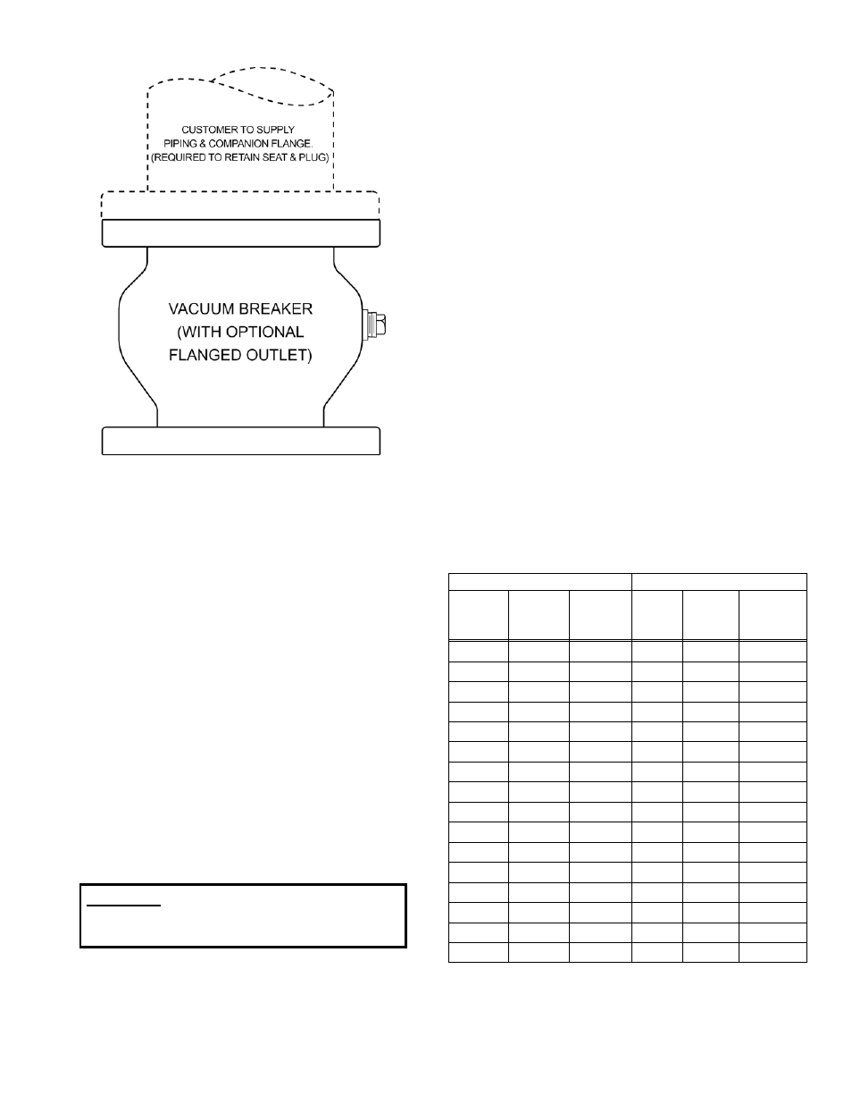
FIGURE 2. VACUUM BREAKER WITH
OPTIONAL FLANGE
INSTALLATION
The installation of the valve is important for its
proper operation. The seat end must be oriented
upward. The valve should be installed on top of
horizontal lines or tanks and equipped with an
isolation valve. If installed in a vault, adequate
ventilation is needed to supply air to the vacuum
breaker.
The valve should be installed to a standard flat-face
flange per ANSI B16.5 or AWWA C207.
When used with an outlet flange, special flange
requirements are given in Drawing SS-1381 on page
3. The mating flange inside diameter must overlap
the valve seat to provide proper seat retention.
Outlet piping and companion flange are required to
retain the seat and disc. Remove the ring flange
and 2 bolts supplied with the vacuum breaker, and
replace with external, full-size flanged piping.
When mating the check valve with butterfly isolation
valves, the clearance between the butterfly disc and
the fully open check valve stem must be checked.
The location of the stem is also shown on the
vacuum breaker submittal drawings. 10 inch and
smaller vacuum breakers have sufficient clearance
for most butterfly valves. However, on 12 inch and
larger valves, the shaft extends beyond the flange
face and may interfere with the operation of adjacent
valves. A short run of pipe or spacer may be
needed between the vacuum breaker and the
isolation valve.
FLANGED ENDS: The flange should be mated with
flat-faced pipe flanges equipped with resilient
gaskets. When ring gaskets are used, the bolt
material shall be ASTM A307 Grade B or SAE
Grade 2 Carbon Steel. Higher strength bolts should
only be used with full-face gaskets.
INSTALLATION: Lower valve over mating flange
using slings or chains around the valve body.
Lubricate the flange bolts and insert them around
the flange. Lightly turn bolts until gaps are
eliminated. The tightening of the bolts should then
be done in graduated steps using the cross-over
tightening method. Recommended lubricated
torques for use with resilient gaskets (75 durometer)
are given in Table 1.
If leakage occurs, allow gaskets to absorb fluid and
check torque and leakage after 24 hours. Do not
exceed bolt rating or crush gasket more than 50 per
cent of its thickness.
125# FLANGE DATA
250# FLANGE DATA
Valve
Size
(in)
Bolt
Dia.
(in)
Bolt
Torque
(ft-lbs)
Valve
Size
(in)
Bolt
Dia.
(in)
Bolt
Torque
(ft-lbs)
2.5 5/8
25-75
2.5 3/4
25-75
3 5/8
25-75
3 3/4
35-75
4 5/8
30-90
4 3/4
50-150
5 3/4
30-90
5 3/4
70-150
6 3/4
30-90
6 3/4
70-150
8 3/4
40-120
8 7/8
90-200
10 7/8
45-150
10 1
110-300
12 7/8
65-200
12 1
1/8
160-450
14 1
80-250
14 1
1/8
140-450
16 1
90-300
16 1
1/4
180-600
18 1
1/8
100-350
18 1
1/4
190-600
20 1
1/8
120-450
20 1
1/4
220-600
24 1
1/4
150-500
24 1
1/2
350-900
30 1
1/4
180-600
30 1
3/4
500-1500
36 1
1/2
250-750
36 2
700-2000
42 1
1/2
300-900
42 2
800-2500
TABLE 1. FLANGE BOLT TORQUES
WARNING: Vacuum Breakers with Flanged
Outlets must have outlet piping
installed or damage may occur.