Installation, Valve construction – Val-Matic 49A Wastewater Air Release Valve User Manual
Page 3
2
CAUTION:
Install valve with "INLET" port
down or leakage will occur.
ITEM DESCRIPTION
MATERIAL
1
Body
Cast Iron
2
Cover
Cast Iron
3
Leverage Frame*
Stainless Steel
4
Seat*
Stainless Steel
5
Float*
Stainless Steel
6
Gasket*
Non-Asbestos
7
Cover Bolt
Alloy Steel
8
Retaining Screw*
Stainless Steel
10
Float Arm*
Stainless Steel
11
Orifice Button*
Buna-N
12
Pivot Pin*
Stainless Steel
13
Retaining Ring*
Stainless Steel
14
Pipe Plug
Iron
17
Float Retainer*
Stainless Steel
18
Lock Nut*
Stainless Steel
19
Link*
Stainless
Steel
20
Extension Shaft*
Stainless Steel
21
Locating Pin
Stainless Steel
22
Orifice Button Arm*
Stainless Steel
28
Pipe Plug
Malleable Iron
30
Washer*
Stainless
Steel
33
Clevis*
Stainless
Steel
34
Lock Washer*
Stainless Steel
35
Retaining Screw*
Stainless Steel
36
Pipe Plug
Malleable Iron
*RECOMMENDED REPAIR PART KIT
INSTALLATION
The installation of the valve is important for its
proper operation. Valves must be installed at the
system high points in the vertical position with the
inlet down. For pipeline service, a vault with freeze
protection, adequate screened venting, and
drainage should be provided. During closure, some
fluid discharge will occur so vent lines should extend
to an open drain area in plant service. A shut-off
valve should be installed below the valve in the
event servicing is required.
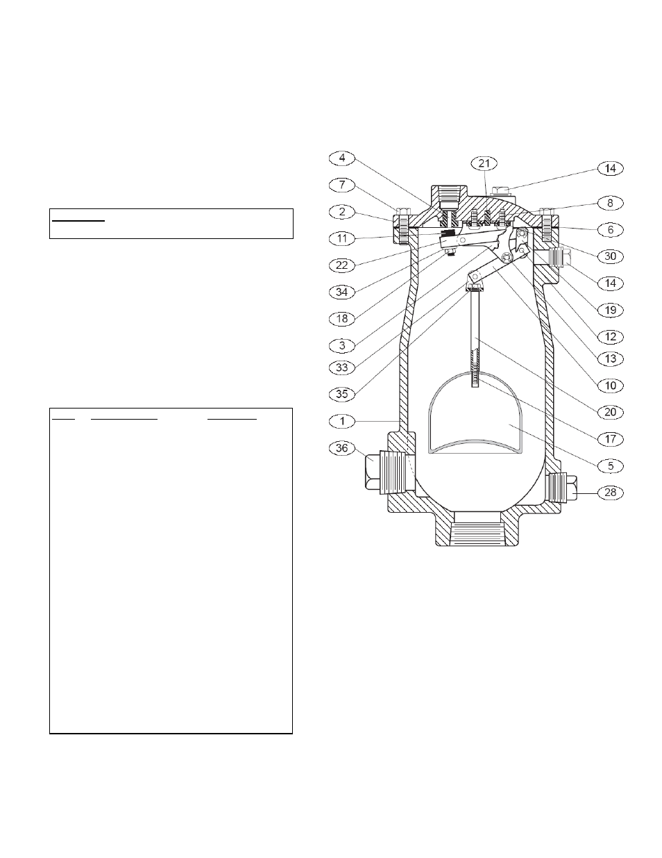
VALVE CONSTRUCTION
The standard Wastewater Air Release Valve body
and cover are cast iron. See the specific Materials
List submitted for the order if other than standard
cast iron construction. All internal components are
stainless steel with the exception of the orifice button
which is resilient. The general details of
construction are illustrated in Figure 2. The body (1)
is threaded for connection to the pipeline. The seat
(4) is threaded into the cast cover (2).
TABLE 1.
LIST OF PARTS
FIGURE 2. WASTEWATER AIR RELEASE VALVE