Pumptec 9025 PRESSURE REGULATING User Manual
Pumptec Hardware
Pumptec, Inc. | 700 McKinley St. NW, Anoka, MN 55303 | 763-433-0303 | www.pumptec.com
Please read and save these instructions. Read carefully before attempting to assemble, install, operate or maintain the
product described. Protect yourself and others by observing all safety information. Failure to comply with instructions
could result in personal injury and/or property damage in which Pumptec, Inc. will not assume any liability for! Retain
instructions for future reference.
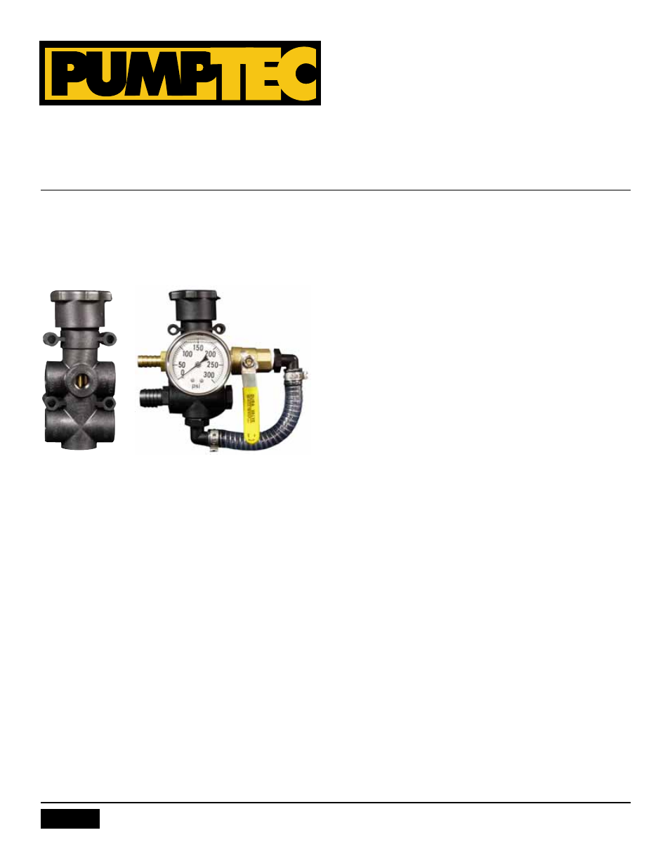
SERIES 9025 PRESSURE REGULATING
MULTI FUNCTION CONTROL SYSTEM (MFCS)
INSTALLATION OF THE 9025 PRESSURE REGULATING
MULTI-FUNCTION CONTROL SYSTEM (MFCS)
1. Locate the pressure regulating MFCS where it is most con-
venient for the operator.
2. Use MFCS mounting holes as a template for marking and
drilling the mounting surface.
3. Attach the MFCS with 4 bolts, washers and lock nuts.
4. Attach ½” discharge hose to pump with hose clamps. Route
discharge hose to the ½” brass hose barb inlet of MFCS. Cut
hose to length. Attach hose with hose clamps.
5. Attach 3/4” bypass hose to 3/4” poly hose barb with hose
clamps. Route 3/4” bypass hose to tank. Cut to length and
in-stall with hose clamp.
NOTE: The MFCS must have open flow in the bypass line. Any
restriction in the bypass return line could cause erratic perfor-
mance or a chattering noise.
OPERATION OF THE SERIES 9025 PRESSURE
REGULATING MULTI-FUNCTION CONTROL SYSTEM
(MFCS)
1. ALWAYS start system with the bypass ball valve open (handle
parallel to ports).
2. ALWAYS run unit for 1-5 minutes to assure all air bubbles and
debris are eliminated.
3. GRADUALLY close bypass ball valve and watch pressure rise.
If pressure rises above desired level, open by-pass ball valve
and loosen pressure adjustment knob.
4. Once the bypass valve can be completely closed, adjust
pressure to desired level.
5. The approximate maximum pressure for the various color
springs is:
Pink 40-50 PSI
Blue 70-80 PSI
Red 140-150 PSI
Silver 210-220 PSI
MONTHLY MAINTENANCE OF THE 9025 PRESSURE
REGULATING MULTI-FUNCTION CONTROL SYSTEM
(MFCS)
1. Remove pressure adjustment knob.
2. Remove spring and brass spring retainer, noting position of
retainer as you remove.
3. Remove piston with needle nose pliers, noting position of
the u-cup as you remove.
4. Clean piston/u-cup assembly and piston/u-cup bore in body
with soft towel.
5. Lubricate piston/u-cup assembly with “Super Lube” or other
similar Teflon/silicone lubricant.
6. Install piston/u-cup into bore using a gentle circular mo-tion.
(You will notice the piston slide into the bore.)
7. Lubricate spring retainer piston socket with “Super Lube”.
8. Install spring retainer with piston socket toward mating part
on piston.
9. Install spring.
10. Lubricate threads in pressure adjustment knob with “Super
Lube”.
11. Install pressure adjustment knob to maximum pressure
setting and then loosen 3 turns.
12. Read and follow operation instructions.
Version 2013