Pumptec 217V SERIES User Manual
Page 7
7
Version 110112
Pumptec Operating Instructions and Parts Manual
PUMP SERIES 112V | 217V
MAINteNANce
DISASSEMblY AnD REASSEMblY
InSTRUCTIOnS (Refer to Schematic)
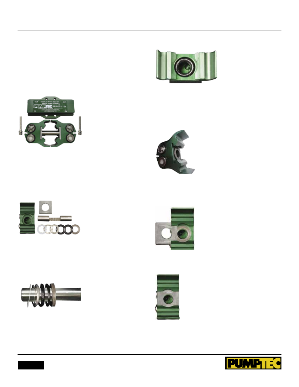
1. Remove pump from motor using a 3/16” hex wrench. Re-
move bolts from pump. Turn pump over so manifold is facing
upward. Place manifold to side as a reference for reassembly.
Figure 1 shows pump separate from motor. Manifold facing
upward and set to side.
Figure 1
2. Holding each head, pull them apart to remove plunger.
Remove retaining plate from pump head. Remove internal
seal parts with finger. Discard parts, but keep head and retain-
ing plate. Figure 2 shows pump heads pulled apart showing
plunger, retaining plate and internal seal.
Figure 2
3. Clean the head with a rag or towel. Inspect for damage or
excess corrosion. If the head is damaged, do not rebuild. (note
the order and orientation of repair parts prior to installation).
Figure 3 shows repair parts in order and in correct orientation.
Figure 3
4. Place one 5/8” ID white washer, one wave washer, one
spreader and two v-packings into bore. Figure 4 shows gasket,
spreader and v-packings placed in bore.
Figure 4
5. Place backing ring on top of v-packings. The backing ring
will not be even with surface and will need to be pushed down
when sliding the retaining plate back into place. Slide the
retaining plate back into place. Figure 5 shows backing ring on
top of seal stack.
Figure 5
Figure 6 shows pushing down edge of backing ring with
retaining plate
Figure 6
Figure 7 shows retaining plate in place
Figure 7
6. Repeat the previous steps 3-5 with the other head.