Parts list: installation instructions, 200 psi illuminated dash panel gauge kit – VIAIR Illuminated Dash Panel Gauge (20065) User Manual
Page 3
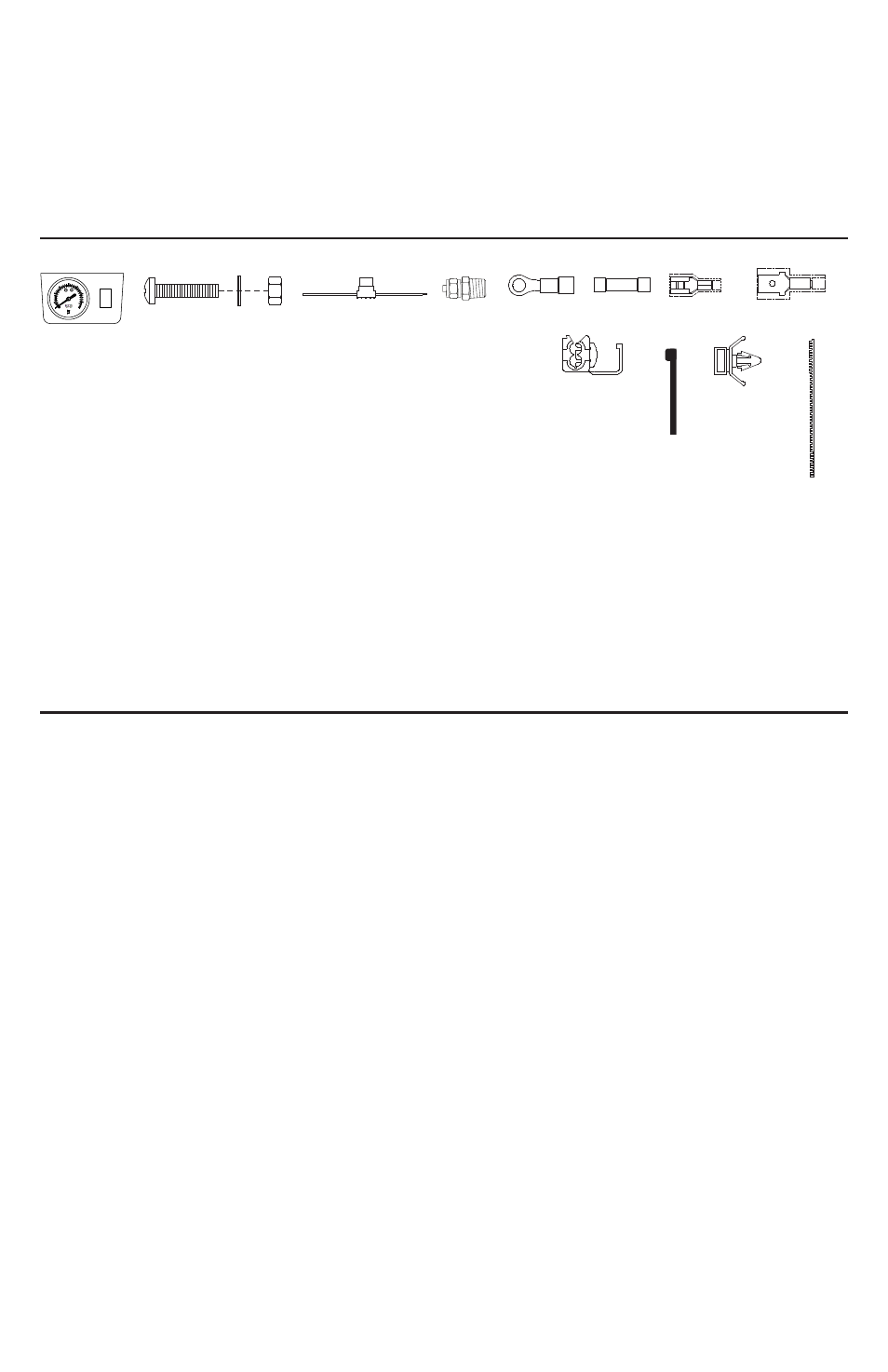
PARTS LIST:
INSTALLATION INSTRUCTIONS:
A. Illuminated Dash Panel Gauge with On/Off Switch (1pc)
B. Mounting Bolts (2pcs)
C. Locking Washer (2pcs)
D. Nuts (2pcs)
E. 20 Ft. Extension Lead Wire with Inline Fuse / Fuse Holder (1pc)
F. 1/8” (F) NPT Compression Fitting for 1/4” O.D. Air Line (1pc)
G. Ring Terminals (3pcs)
H1. Insulated Female Terminal Connectors (2pcs)
H2. Insulated Female Terminal Connector (1pc)
I. Insulated Male Terminal Connectors (2pcs)
J. Quick Splice Connectors (2pcs)
K. Cable Ties (6pcs)
L. Cable Tie Brackets (3pcs)
M. Continuous Grommet (1pc)
CHECK FOR CORRECT GAUGE KIT: The Illuminated Dash Panel Gauge Kit (P/N 20065) was
designed for Onboard Air Installation.
THIS ILLUMINATED DASH PANEL GAUGE KIT SHOULD BE USED IN CONJUNCTION WITH A
PRESSURE SWITCH AND RELAY OR A PRESSURE SWITCH WITH A BUILT-IN RELAY.
IMPORTANT: The Illuminated Dash Panel Gauge has been fully function tested and calibrated for
accuracy. The air inlet on this gauge has a factory installed compression fitting. DO NOT ATTEMPT
to tighten or loosen the body of this compression fitting. Any adjustments will likely cause the gauge
to malfunction and void warranty.
(See Fig. 3)
NOTE: The Illuminated Dash Panel Gauge included in this kit is rated for 200 PSI. DO NOT
pressurize gauge to more than 200 PSI. Over-pressurization will cause the gauge to malfunction
and void warranty.
200 PSI Illuminated Dash Panel Gauge Kit
B
C
D
E
F
A
5
0
0
35
15
10
1
20
25
30
2
G
H1
H2
I
J
K
L
M
Please read this instruction manual carefully prior to operating this product.
Pay particular attention to the
CAUTION and WARNING statements in this manual.
Failure to comply with these instructions could result in personal injury or property
damage. Retain these instructions for future reference.
USER MANUAL