Mounting and wiring – VIAIR 450H User Manual
Page 3
MOUNTING AND WIRING
1. Disconnect ground cable from vehicle’s battery.
2. Temporarily position the air compressor in the location where it will be mounted. Route the
positive wire to the positive post of the battery. Measure and cut positive wire to the appropriate
length and use appropriate inline fuse.
3. Route ground wire to the negative post of the battery or to an appropriate chassis grounding
point and cut ground wire to length as needed.
4. Mount the air compressor by using the pair of anti-vibration mounting brackets and four sets
of 13/64” (5mm) bolts, nuts, washers, and locking washers provided. Use 13/64” drill bit to drill
holes for the first set of brackets. Mount this first bracket with screws, flat washers, locking
washers and nuts provided. (Refer to Fig. 2 for placement of washers.)
5. Place compressor into mounted bracket. Place second set of bracket under the air compressor,
make sure that the compressor sits snuggly in between the two brackets. Mark off holes to be
drilled using the second set of brackets as guides. Drill holes, and place compressor snugly
between brackets and mount the second bracket.
6. Refer to Remote Air Filter Installation Instructions included in the Remote Inlet Air Filter Pack
for installation of Remote Inlet Air Filter.
7. This air compressor comes equipped with a 1.5 ft. heavy duty heat resistant leader hose.
This leader hose is designed to provide easy access for air hose attachment and to prolong the
life of your extension hose as well as minimizing wear to the compressor air outlet. Do not
remove this leader hose from the air compressor.
8.
PLEASE NOTE: The leader hose that comes with your compressor may have a
built-in inline check valve installed. Do not remove inline check valve from leader hose.
9. Select a proper location to mount leader hose with hose bracket provided.
Avoid locations where leader hose may become tangled with wires and other hoses.
10. To mount hose bracket, drill hole with 3/16” drill bit and push self–anchoring hose bracket pin
into hole. Route leader hose through hose bracket and secure hose by pressing bracket clamp
into locked position.
11. To remove hose from the hose bracket, simply press down on the hose clamp release tab to
release bracket clamp. (Fig. 3)
12. Attach ground wire to the negative post of the battery or chassis grounding point.
Check to make sure that the air compressor’s ON/OFF switch is in the OFF position.
Attach positive wire to positive terminal of the battery.
13. Re-check to make sure that all connections are made securely.
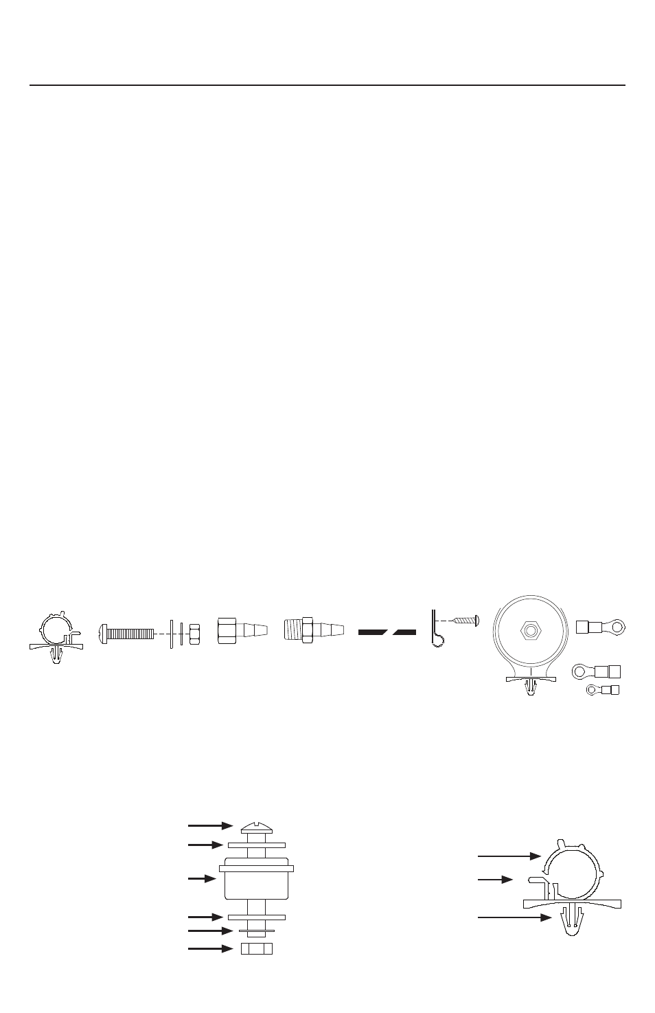
(Fig. 1) 400H/450H Hardmount Air Compressor Kit Installation Parts List:
M
A. Hose Bracket (1 pc)
B. Mounting Bolts (4 pcs)
C. Flat Washers (8 pcs)
D. Locking Washer (4 pcs)
E. Nuts (4 pcs)
F. 1/4” F x 3/8” Tube Fitting (1 pcs)
G. 1/4” M x 3/8” Tube Fitting (1 pcs)
H. 3/8” Air Line (1 pc)
I. Air Line Clips (3 pcs)
J. Screws (3 pcs)
K. Remote Inlet Air Filter with Filter Element (1 pc)
L. Positive (Red) Ring Terminal (1pc)
M. Negative (Black) Ring Terminals (2 Sizes)
400H - 450H Air Compressor Kit
USER MANUAL
A
B
D
F
G
I
J
K
H
B
C
C
D
E
F
(Fig. 2) Compressor
Mounting Hardware
B. Mounting Bolt
C. Flat Washer
D. Locking Washer
E. Nut
F. Vibration Isolator
(Fig. 3) Leader Hose Bracket
L. Hose Clamp
M. Clamp Release Tab
N. Self-Anchoring Pin
L
M
N
L