Mounting and wiring – VIAIR 480C User Manual
Page 3
MOUNTING AND WIRING
1. Disconnect ground cable from vehicle’s battery.
2. Temporarily position the air compressor in the location where it will be mounted.
3. Route ground wire to the negative post of the battery or to an appropriate grounding point and
cut ground wire to length as needed.
4. Mount air compressor with the four sets of bolts, nuts, washers, and locking washers provided.
(See Fig. 2 for Mounting Instructions) Use of thread sealant is recommended.
5.
NOTE: For Remote Inlet Air Filter Installation, refer to Remote Inlet Air Filter Installation
Instruction included in the Remote Inlet Air Filter Pack.
6. VIAIR air compressor(s) come equipped with heavy duty heat resistant leader hose(s) with
either 1/4” or 3/8” NPT fittings. This leader hose is designed to prolong the life of your air line.
Do not remove this leader hose from air compressor.
7.
IMPORTANT: Please note, the leader hose that comes with your compressor has a built-in inline
check valve. Do Not remove inline check valve from leader hose.
8. Select proper location to mount leader hose with hose bracket provided. Avoid locations where
leader hose may become tangled with wires and other hoses.
9. To mount hose bracket, drill hole with 3/16” drill bit and push self–anchoring hose bracket pin
into hole. Route leader hose through hose bracket and secure hose by pressing bracket clamp
into locked position.
10. To remove hose from the hose bracket, simply press down on the hose clamp release tab to
release bracket clamp. (Fig. 3)
11. Connect compressor’s positive lead wire to one of the leads of your pressure switch.
12. Make sure that your compressor setup is properly fused. For appropriate fuse size, refer to
amp draw of compressor in the specifications section of this manual.
13. Always locate fuse as close as possible to power source.
14. Before connecting to power source, re-check to make sure that all connections are
made properly.
15. Connect and test compressor system by running the compressor for a short time to build up
pressure in your air tank.
16. Once air pressure reaches preset cut out pressure of your pressure switch, the compressor
will shut off. Inspect all air line connections for leaks with soap and water solution. If a leak
is detected, the air line may not be cut squarely or pushed all the way in. Repair connections
as needed.
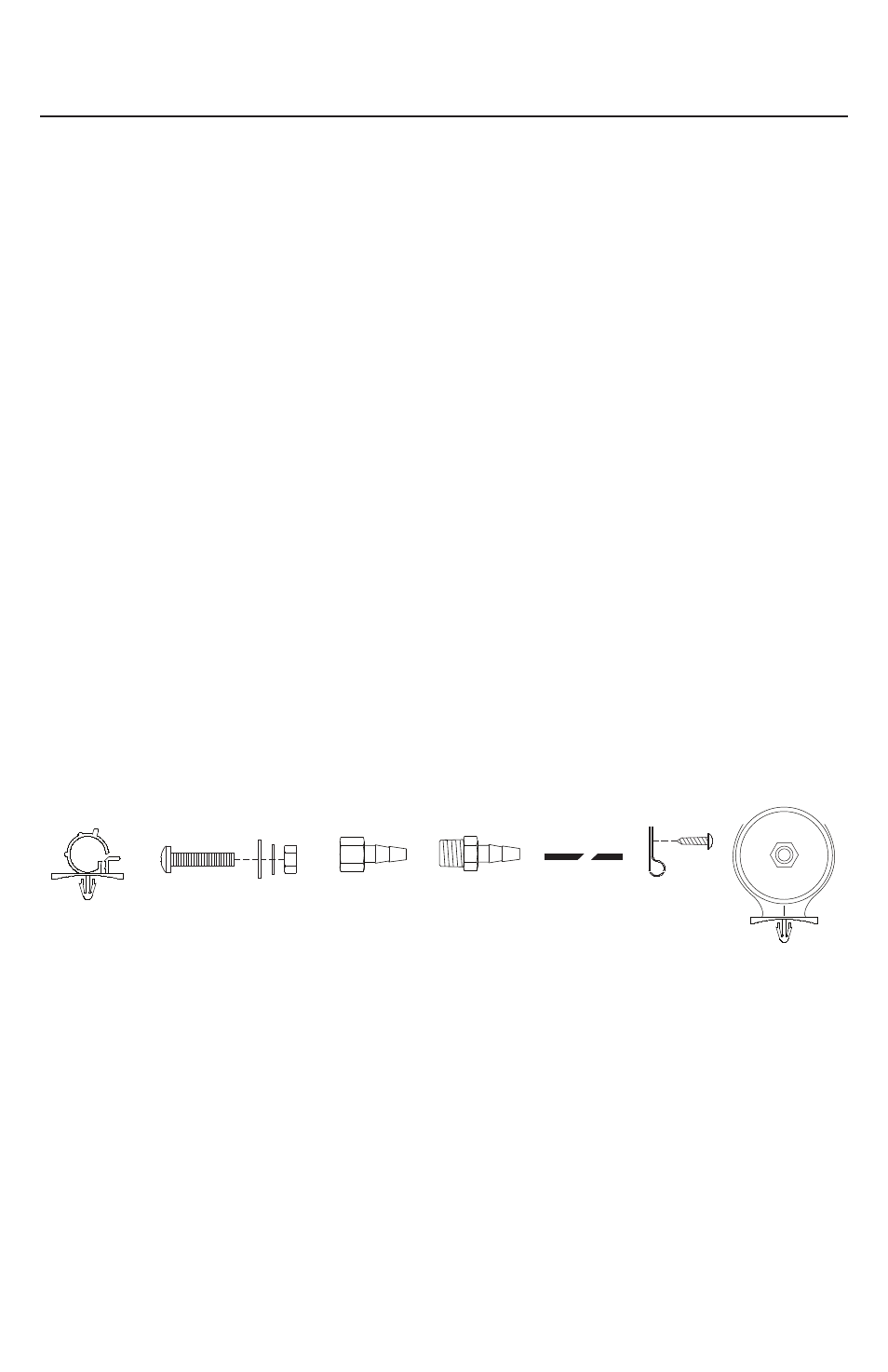
(Fig. 1) 380C / 480C Compressor Installation Parts List:
A. Hose Bracket (1pc)
B. Mounting Bolts (4pcs)
C. Flat Washers (8pcs)
D. Locking Washers (4pcs)
E. Nuts (4pcs)
F. 3/8” NPT F x 1/2” Barbed Fitting (1pc) (480C)
1/4” NPT F x 1/2” Barbed Fitting (1pc) (380C)
G. 3/8” NPT M x 1/2” Barbed Fitting (1pc) (480C)
1/4” NPT M x 1/2” Barbed Fitting (1pc) (380C)
H. Remote Mount Filter Air Line (1pc) (380C)
I. Air Line Clips (3pcs)
J. Screws (3pcs)
K. Remote Inlet Air Filter with Filter Element (1pc)
USER MANUAL
380C - 480C COMPRESSOR KIT
C
E
B
A
D
F
G
I
J
K
H