2 normal operation, 1 unstow, 2 orientation – Advantech 120 User Manual
Page 12
ENTERPRISE120
UK Office Phone +44 1480 357 600
Fax +44 1480 357 601
US Office Phone +1 480 839 4136
Fax +1 480 839 0860
Canada Office Phone +1 514 420 0045
Fax +1 514 420 0073
E-mail [email protected]
Website: www.AdvantechWireless.com
Page 12 of 14
Ref: PM-ENT120-002-11022
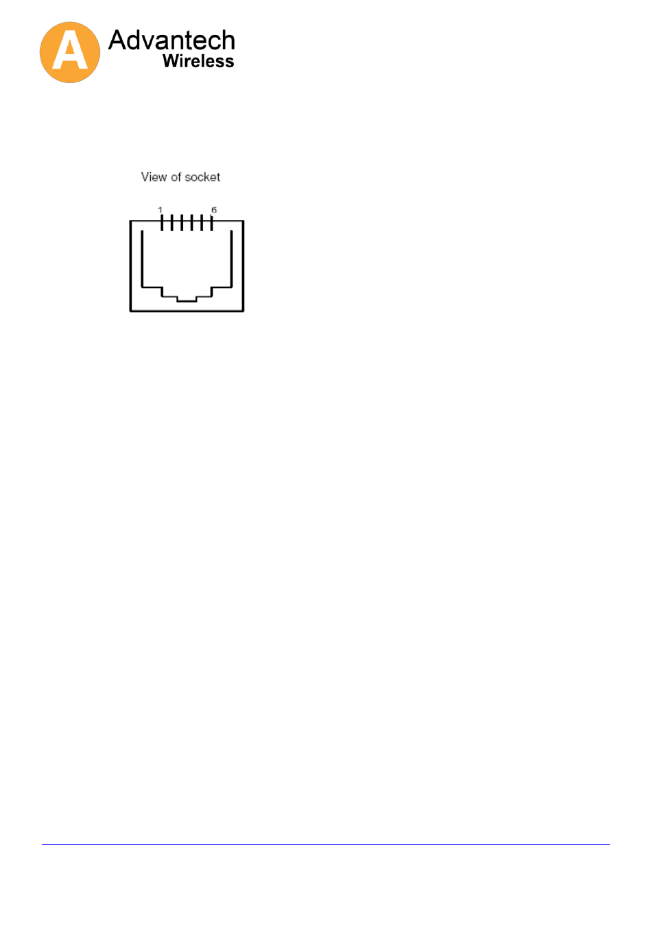
D Connector Signal RJ-11 Connector
Pin 5 Ground Pin 1
Pin 3 Term Data OUT Pin 2
Pin 2 Term Data IN Pin 3
Pin 6 Not Used Pin 4
Pin 1 Common Pin 5
Do Not Connect + 5VDC @ 100 mA Pin 6
This diagram shows the pin order when viewed from
plug cable entry.
2 Normal Operation
The i-Point's normal "deploy" operation is made up of several stages.
There is information provided at some stages which can be helpful to diagnose a system having
problems.
First start to capture the information on the serial port. (In hyper-terminal use the "Transfer\Capture
text" menu and provide a filename.) If you need assistance interpreting the information then it can be
e-mailed to
.
Then type the command "
debugport 0
". This will instruct the system to provide additional diagnostic
data.
Then type the command "
deploy
".
2.1 Unstow
No useful information about this step. The antenna is driven from the current position to the "unstow"
position.
2.2 Orientation
During this step 3 pieces of information are gathered.
1. The GPS is read to get the current location on earth.
2. The magnetometer is read to get a heading angle for the platform. This is the geographical
direction that the antenna is pointing at the unstow position.
3. Then the antenna is driven to an elevation angle above the geostationary arc to take a "noise floor"
measurement.
Once this drive has been completed the GPS and the magnetometer readings can be checked.
To see the gps data type the command "
gps
". Check that the last line indicates that the signal is valid.