Hdmi pin definition, Hardware installation – LevelOne HVE-9005 User Manual
Page 9
7
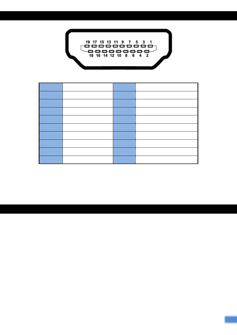
HDMI PIN DEFINITION
Type A (Receptacle) HDMI
Pin 1
TMDS Data2+
Pin 11 TMDS Clock Shield
Pin 2
TMDS Data2 Shield
Pin 12 TMDS Clock
–
Pin 3
TMDS Data2
–
Pin 13 CEC
Pin 4
TMDS Data1+
Pin 14 Reserved (N.C. on device)
Pin 5
TMDS Data1 Shield
Pin 15 SCL
Pin 6
TMDS Data1
–
Pin 16 SDA
Pin 7
TMDS Data0+
Pin 17 DDC/CEC Ground
Pin 8
TMDS Data0 Shield
Pin 18 +5V Power
Pin 9
TMDS Data0
–
Pin 19 Hot Plug Detect
Pin 10
TMDS Clock+
HARDWARE INSTALLATION
1. Connect a HDMI or DVI source (such as a Blu-ray Disc player) to the transmitting unit
HVE-9005T.
2. Connect a HDMI or DVI display (such as a LCD TV) to the receiving unit HVE-9005R.
3. Connect IR Blaster/Receiver to both T and R units.
4. Connect a Cat-5/5e/6 cable between the transmitting and receiving units.
5. Make sure this Cat-5/5e/6 cable is tightly connected and not loose.
6. Plug in
5V DC power supply unit to the power jack of the receiving unit HVE-9005R and the
transmitting unit HVE-9005T.