Rear panel – Inter-M ARM-911 User Manual
Page 8
AUTOMATED REMOTE MESSAGE
5
ARM-911
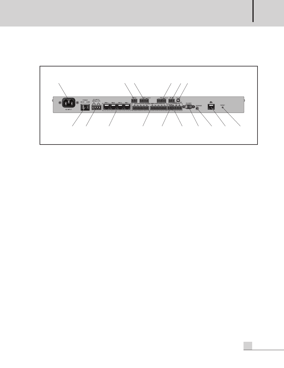
Rear Panel
Rear Panel
1. AC INLET
Connect the power cable which is supplied with the unit.
2. POWER SW
Use this switch to turn the power on or off.
.
3. DC INPUT
Connect a DC24V power source to this terminal.
Make sure the polarity when make a connection.
4. RM INPUT TERMINAL
Connect the RM-911D or RM-911W to this terminal.
Be sure for the CAT5E cable not to exceed the maximum operable distance.
*Maximum length of CAT5E cable between ARM-911 and RM-911.
Cable resistance ≤ 30Ω: 300m
30Ω < cable resistance ≤ 80Ω: 100m
5. CONTACT INPUT
To play the file directly which is in the SD card, make a short of the each input contact.
6. CONTACT OUTPUT
If the contact output is set using GUI, then the contact is output when the message is played.
7. FAULT INPUT / OUTPUT
If the Fault input pins are opened, then the window displays ‘FAULT-IN’.
If the Fault input pins are shorted, then it is nornmal state.
NC means Normally Closed, when it is in fault status it is opened.
NO means Normally Opened, when it is in fault status it is closed.
1
2
3
4
5
7
13
14
15
16
12
11
10
8
9
6