Typical system connections -12 – Audiovox VOH802 User Manual
Page 13
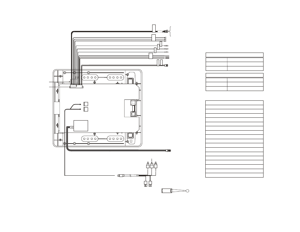
TYPICAL SYSTEM CONNECTIONS
-12-
1
2
3
4
5
6
12
10
7
8
9
15
16
17
13
14
TO
FM
TR
AN
SM
ITT
ER
SP
EA
KE
R
OR
HE
AD
PH
ON
E
CO
NN
EC
TIO
N
LIN
E
OU
T-R
LIN
E
OU
T-V
LIN
E
OU
T-L
TW
O
DO
M
E
LIG
HT
’S
CO
NN
EC
TIO
N
PO
W
ER
(+
12
V)
PO
W
ER
(G
ND
)
White RCA(Audio Left)
Red RCA(Audio Right)
Yellow RCA(Video)
4 PIN
Power
Connector
2 PIN IR
Connector
Accessor
Harness
18
11
PIN 2 – Power GND/Black
PIN 3 – Dome Light ON – Red/Black
PIN 4 – Lamp Common – Black/Red
PIN 5 – Dome Light Auto – Purple/Brown
PIN 6 – Line Out (L)/White
PIN 7 – Spk Out (R) /Green
PIN 8 – Spk Out-GND/Black
PIN 9 – Spk Out (L)/Grey
PIN 10 – Video Out/Yellow
PIN 11 – Video GND/Black
PIN 12 – Line Out (R)/Red
PIN 13 – Power 12V(FM Trans.)/Red
PIN 14 – Power GND (FM Trans.)/Black
PIN 15 – Audio (L) Out (FM Trans.)/White
PIN 16 – Audio GND (FM Trans.)/Black
PIN 17 – Audio (R) Out (FM Trans.)/Red
PIN 18 – Line Out GND/Black
PIN 1 – Power/Red
Lamp Auto
Purple/Brown
Constant 12V Black/Red
Lamp ON
Red/Black
Negative Dome Light Switching
Lamp Auto
Purple/Brown
Ground Black/Red
12Vdc
Red/Black
Positive Dome Light Switching
IR Transmitter LED