C. hot water outlet – HTP GL-175 User Manual
Page 7
7
LP-181 Rev. 3.25.14
prevent short circulating the tankless coil. This may cause poor supply pressure, or noisy operation, depending upon the type of
installation.)
On the tank, tankless outlet, use both thread tape and pipe dope and connect a ¾” NPT brass tee. On the run, install a brass drain
valve. In the branch, install a ¾” (minimum) tube adapter, and connect this to the hot tankless coil outlet on the boiler.
NOTE: Se
e “TYPICAL INSTALLATION”, Figure 3.
C. HOT WATER OUTLET
Use both thread tape and pipe dope to connect an NPT brass tee (refer to dimensional information chart for the correct connection
size).
In the run of the brass tee, install an NPT brass temperature and pressure (T&P) long element for hot water storage tanks, required by
local codes, but not less than a valve certified for meeting the requirements for relief valves for hot water heaters (ANSI Z21.22 and
CAN1-4.4) by a nationally recognized lab that maintains periodic inspection of production of listed equipment. Make sure the valve is
sized to the BTU and storage capacity of the storage tank. The T&P valve must be plumbed down, so discharge will exit at least
6”
above the structural floor and not contact any live electrical parts.
NOTE:
See “TYPICAL INSTALLATION” drawing, Figure 3.
Do not thread a cap or plug into the relief valve under any circumstances! Explosion and property damage, serious injury, or death may
result.
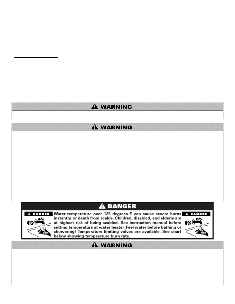
To avoid water damage or scalding due to relief valve operation:
Discharge line must be connected to relief valve outlet and run to a safe place of disposal. Terminate the discharge line in a
manner that will prevent possibility of severe burns or property damage should the relief valve discharge.
Discharge line must be as short as possible and the same size as the valve discharge connection throughout its entire length.
Discharge line must pit
ch downward from the valve and terminate at least 6” above the floor drain, making discharge clearly
visible.
The discharge line shall terminate plain, not threaded, with a material serviceable for temperatures of 375
o
F or greater.
Do not pipe discharge to any location where freezing could occur.
No valve may be installed between the relief valve and storage tank or in the discharge line. Do not plug or place any
obstruction in the discharge line.
Test the operation of the relief valve after filling and pressurizing the system by lifting the lever. Make sure the valve
discharges freely. If the valve fails to operate correctly, immediately replace with a new properly rated relief valve.
Test T&P valve at least once annually to ensure the waterway is clear. If valve does not operate, turn the heating system
“off”
and call a plumber immediately.
Take care whenever operating relief valve to avoid scalding injury or property damage.
FAILURE TO COMPLY WITH THE ABOVE GUIDELINES COULD RESULT IN FAILURE OF RELIEF VALVE OPERATION,
RESULTING IN POSSIBILITY OF SUBSTANTIAL PROPERTY DAMAGE, SEVERE PERSONAL INJURY, OR DEATH.
RE-INSPECTION OF T&P RELIEF VALVES: T&P valves should be inspected AT LEAST ONCE EVERY THREE YEARS, and
replaced, if necessary, by a licensed plumbing contractor or qualified service technician, to ensure that the product has not been
affected by corrosive water conditions and to ensure that the valve and discharge line have not been altered or tampered with illegally.
Certain naturally occurring conditions may corrode the valve and its components over time, rendering the valve inoperative. Such
conditions can only be detected if the valve and its components are physically removed and inspected. Do not attempt to conduct an
inspection on your own. Contact your plumbing contractor for a re-inspection to assure continued safety.
FAILURE TO RE-INSPECT THIS VALVE AS DIRECTED COULD RESULT IN UNSAFE TEMPERATURE AND/OR PRESSURE
BUILDUP WHICH CAN RESULT IN SEVERE PROPERTY DAMAGE, SERIOUS PERSONAL INJURY, OR DEATH.