H. venting drawings – HTP 199-55SA User Manual
Page 30
30
LP-179 REV. 3.21.14
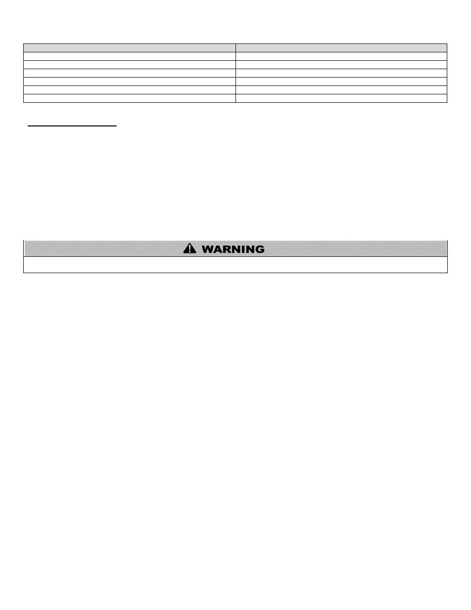
DESCRIPTION
STOCK CODE
2” PVC CONCENTRIC VENT TERMINATION KIT
KGAVT0501CVT
3” PVC CONCENTRIC VENT TERMINATION KIT
KGAVT0601CVT
2” STAINLESS STEEL VENT TERMINATION KIT
V500
3” STAINLESS STEEL VENT TERMINATION KIT
V1000
4” STAINLESS STEEL VENT TERMINATION KIT
V2000
3” POLYPRO VENT KIT
8400P-001
Table 8
H. VENTING DRAWINGS
1. DIRECT VENT INSTALLATION OF EXHAUST VENT AND INTAKE PIPE
If installing a direct vent option, combustion air must be drawn from the outdoors directly into the water heater intake, and exhaust must
terminate outside. There are three basic direct vent options detailed in this manual: 1. Side Wall Venting, 2. Roof Venting, and 3.
Unbalanced Venting.
Be sure to locate the heater such that the exhaust vent and intake piping can be routed through the building and properly terminated.
Different vent terminals can be used to simplify and eliminate multiple penetrations in the building structure (see Optional Equipment in
Venting Section). The exhaust vent and intake piping lengths, routing and termination methods must all comply with the methods and
limits given in the Venting section, Part 5 of this manual.
When installing a combustion air intake from outdoors, care must be taken to utilize uncontaminated combustion air. NOTE: To
prevent combustion air contamination, see Table 1
Take extra precaution to adequately support the weight of vent pipes terminating through the roof. Failure to properly support roof
terminated vent piping could result in property damage, serious personal injury, or death due to flue gas leakage.