HTP Flexible Vent Kit User Manual
Page 5
5
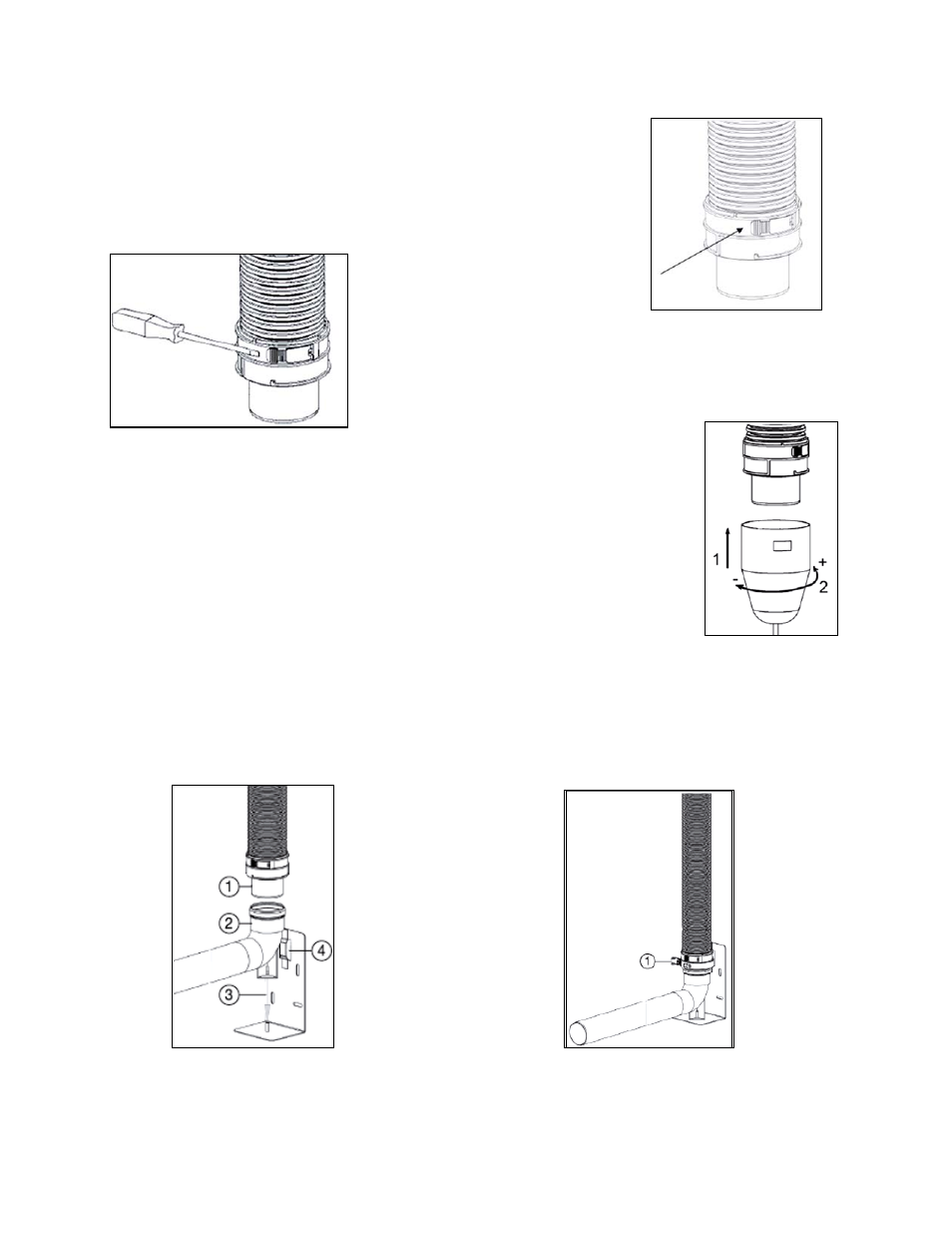
6. Fix the adapter on the liner with the latching tabs (Fig. 4).
7. It is possible to loosen the latching
tabs with a screw driver. See Fig. 5.
8. Mount the flexible spacer brackets with a maximum distance of 6
feet (2 m) between each.
9. The optional pull cone installation aid (Part #8400P-013) must be connected
using a bayonet connection with a rotating movement of ¼ turn to the right (+).
Install the liner from the top. See Fig. 6.
10. The flexible liner must be installed from the top of the shaft into the installation
room. To prevent damage to the liner, a second person must guide the liner from
the top in the middle of the shaft.
11. After installing the required length of liner, remove the mounting aid by rotating ¼ turn
counterclockwise (-). Then attach the rigid-flex adapter into the support bend. See Fig. 7.
a. Position the support elbow on the support bracket (see 2 and 3, Fig. 7).
b. Secure the support elbow with the clamp (see 1, Fig. 8) around the flex-rigid adaptor (see 1, fig
7) and through the slot of the support console (see 4, Fig. 7).
Figure 7 – Installation of Support Elbow
Figure 8 – Securing the Support Elbow
Figure 4 – Fixing the Adapter
Figure 5 – Loosening the
Latching Tabs
Figure 6 – Pull Cone