Inhalable dust sampling using the i.o.m. sampler – SKC Limited Sidekick Pump Step By Step Guide User Manual
Page 6
Page 4
224-G2 Issue B
www.skcltd.com
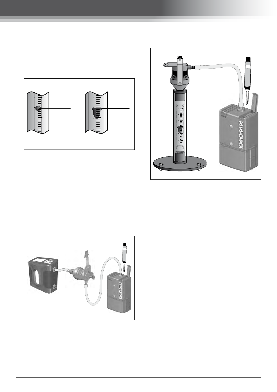
Inhalable Dust Sampling using the I.O.M. Sampler
type rotameter is usually marked with a number
of dots. The dots give indication that the float
is spinning in the airflow, thus showing that it
is not touching the walls of the rotameter tube
which could affect the accuracy of the reading.
Note that the rotameter must be placed onto a
flat, level surface to ensure that the float does
not touch the sides of the rotameter tube.
2
2
1
1
5
0
5
0
2
2
1
1
5
0
5
0
Read Here
Read Here
Ball Type
Float Type
4. The I.O.M. sampler with filter fitted is placed
onto the foam sealing pad on the top of the
calidaptor. Secure the I.O.M. sampler to the
calidaptor using the finger screw, ensuring a
good seal of the front face of the I.O.M. sampler
to the foam pad. The hosetail fitting supplied
with the calidaptor is screwed into the hole in the
bottom of the calidaptor. The calidaptor hosetail
is connected to the hosetail on the Defender
primary calibrator marked ‘Suction’, with the
length of tubing supplied with the calidaptor.
Turn on the Defender primary calibrator
and set it to take continuous flow readings.
5. If using a rotameter to set the flow rate, the
calidaptor is designed to screw directly into the
inlet in the top of SKC rotameters. Unscrew the
hosetail fitting supplied with the rotameter, and
screw the calidaptor into the threaded hole in the
top of the rotameter, fastening tightly to ensure
a good seal. If using a non-SKC rotameter, use
the hosetail fitting and length of tubing supplied
with the calidaptor to connect the calidaptor
to the rotameter. Fit the I.O.M. sampler to the
calidaptor and secure with the finger screw.
0
5
0
5
0
5
3
3
2
2
1
1
0
0
6. The pump flow rate is adjusted using the
smallest bladed screwdriver attachment of the
toolkit supplied with the pump. Lift up the hinged
clear cover on the top of pump, and switch on
the pump using the on/off push-button. Use the
screwdriver tool to turn the adjustment screw
adjacent to the on/off push-button. As the screw
is turned the flow reading on the flow calibrator
should increase or decrease. If this does not
happen check the system for leaks or blockages.
One common cause of lack of flow is by using
the separation papers (usually coloured blue)
sometimes found in boxes of filters, instead of
the filters themselves (usually white). Once the
flow is set to the required level of 2.0 litre/min,
switch the sample pump off.
7. Remove the I.O.M. sampler from the calidaptor
and then remove the filter cassette from the
sampler. Remove the filter paper from the
cassette, and ensure that the cassette inlet
spout and support grid are clean and free of
contamination. Fit the second filter paper into
the cassette. Pre-weigh the filter and cassette,
and then fit the cassette back into the I.O.M.
sampler. Check the flow once again with the pre-
weighed filter and cassette in place and make
any final adjustments needed to bring the flow
to the required level. It is advisable to do this
as quickly as possible to minimise the chance
of collecting anything that may affect the final