Operation, Start-up, Basic operations – Ransburg 9060 LV Cascade Controller 80120-XXX User Manual
Page 34: 9060 cascade low voltage controller - operation, Start-up display
9060 Cascade Low Voltage Controller - Operation
29
CP-13-02.3
OPERATION
START-UP
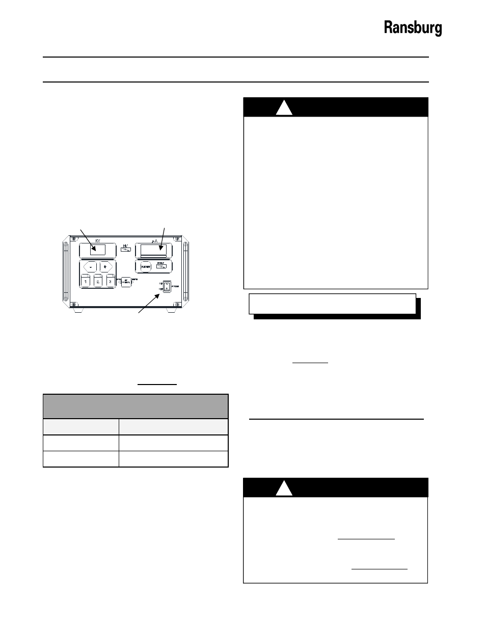
After all installation procedures are completed,
operation of the applicator may begin. When
the ON-OFF switch is turned on, the kV display
will show the applicator type the 9060 Controller
is configured for and the µA (microamp) display
will show the current software revision level as
shown in Figure 18. These items are displayed
for approximately 5 seconds.
The following table lists the applicator types
shown on the display as per the current revi-
sion of this manual as a reference.
START-UP DISPLAY
Applicator Type
Description
ES
Evolver SE/Estaquick
Ab
Aerobell 168
VERIFY that the gun jumper configura-
tion is set for the applicator type that is
being used for the system based on the
Applicator Type displayed during start-up.
DO NOT adjust the gun configuration
jumpers J10-J13. If they are incorrect,
contact your Ransburg representative.
USE ONLY the gun type configuration
for the specific applicator being used. Us-
ing the wrong configuration may allow for
operation outside the recommended pa-
rameters and values for the applicator
and can result in damage or un-safe op-
eration
.
!
W A R N I N G
BASIC OPERATIONS
The basic operations are general operations
that are available in both REMOTE and LOCAL
modes.
Figure 18: Controller Start-Up Display
Gun Type Number
On-Off Switch
Software Rev. Lev-
After the initial start-up delay, the unit will be
configured for the applicator based on the gun
type jumper settings. It will then enter LOCAL
mode, unless a REMOTE mode signal is
already present. At this point the unit is ready
for standard operation.
During start-up, the gun trigger or remote
trigger input should NOT be active. An ac-
tive trigger signal will cause a non-
resettable boot fault (bF) and prevent the
unit from being operated. This is designed
to prevent unintended firing of the high-
voltage immediately after start-up. Please
refer to the “Fault Section” of this manual
for more information.
N O T E
(For 80100-51X Units ONLY)
Every time the high voltage is triggered
(turned on), there is a 4 second timer that
inhibits the DI/DT overload and current
overload faults while the applicator is be-
ing charged. Ensure that NO OBJECTS
approach the bell during charging.
!
W A R N I N G