Gentec-EO T-Rad-USB (LEMO) User Manual
Page 8
T-RAD-LEMO-USB Instruction Manual Version 2.0
June 2012
8
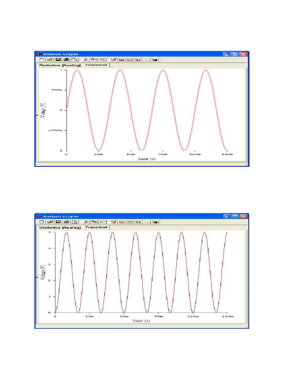
The reference signal supplied by the lock in signal has peak amplitude of 1V and a frequency of
25Hz and is shown in figure 2.
Figure 2 Reference Signal
After multiplying the two signals using a circuit called a Phase Specific Detector in ananalog lock in, or by
direct math in a digital lock in, the output signal is shown in figure3. Note that its peak to peak amplitude is
5V, or ½ of the input and its frequency is 50Hz,or twice the input frequency. Also note it now has a DC
offset of the peak voltage of the input signal divided by 2 as predicted. This DC offset is what the low pass
filter will pull from figure 3.
Figure 3 Result of Multiplication