Fairbanks 6020 Series Titan Motor Truck Scale User Manual
Page 15
c.
Smart Sectional Controller
Wire cells into each section’s sectional controller per the appropriate service manual.
Refer to the Appendix for typical wiring information.
Load Cell Wiring Designations
Color
Description
Black
(-) Excitation
Green
(+) Excitation
Red
(-) Signal
White
(+) Signal
Yellow
Shield
50745
15
03/10 Rev. 5
Note: The Titan has been designed to provide protection from the effects of moisture.
The load cells have been calibrated with the cable attached, and therefore the cable
should NOT be cut. The cable is connected directly to the sectional controller
through a sealed gland fitting which MUST be tightened properly to keep water and
moisture out of the box. All cabling should have a drip loop at the cell or box entry
location to help prevent water entry. On all boxes, the load cell cable gland fittings
have O- rings that can be forced out of position if tightened improperly. To prevent
this, first tighten the inner nut securing the gland in the hole, then insert the cable
and carefully tighten the gland. Do not over-tighten where the gland turns .
The cover MUST be secured with ALL screws tightened properly (10 in/lbs) for
protection against moisture.
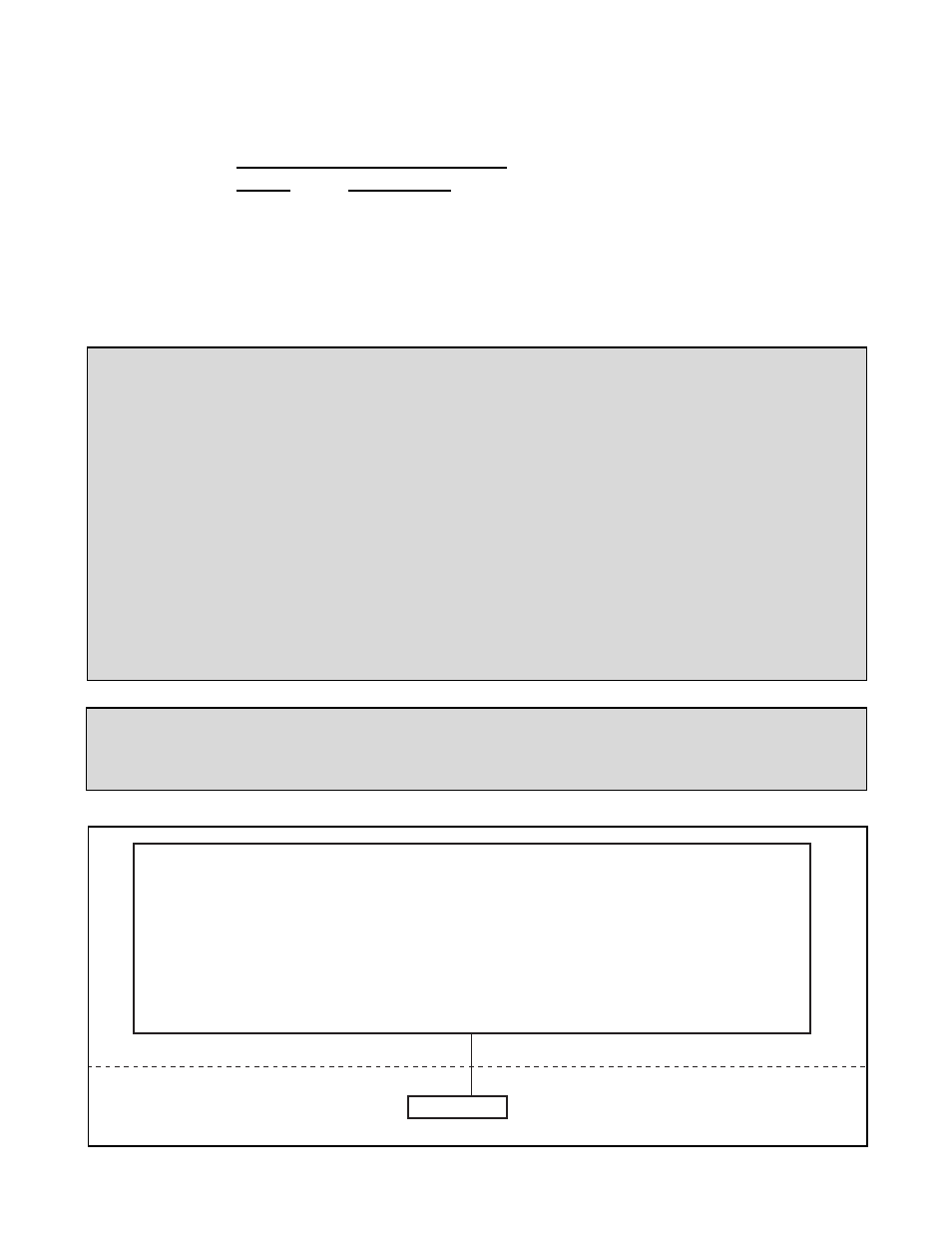
Note: Smart Sectional Controllers have connections for two (2) load cells, TB1 and TB2.
The odd numbered cell connects to TB1 and the even numbered cell connects to TB2.
1 3 5 7
2 4 6 8
Indicator
Scale house
50693-1
50746-12