General Technologies FF310 Fault Finder for Electrical Wiring Open / Short Circuit User Manual
Page 3
Page 3
Page 2
4 - Setting the sensitivity level
The FF310R has three user selectable sensitivity ranges: ‘
Low’, ‘Medium’ and ‘High’.
These ranges allow the technician to choose the degree of sensitivity most suitable to
the particular detection being performed.
4.1 Checking the current sensitivity setting:
The FF310R’s current sensitivity setting is displayed when the “ON/OFF” button is pressed
for 2 or 3 seconds while the unit is ‘ON’ (steady green indicator on). The high sensitivity
setting generates a quick triple flashing of the green LED, a double flashing in the medium
sensitivity range and a single flashing indicates a low sensitivity level setting.
Green LED shows a:
FF300R Tracer set to:
Single (1) flash and beep
Low sensitivity
Double (2) flash and beep
Medium sensitivity
Triple (3) flash and beep
High sensitivity
When turned off, the FF310R will retain the last selected sensitivity setting.
4.2 Procedure to select the FF310R’s range :
1. Unit should be on, if not, turn it on by momentarily pressing the
“
ON/OFF” button.
2. Press and Hold “
ON/OFF” button for approximately 3 seconds until a beeping and
flashing occurs. This initial beeping and flashing indicates the current sensitivity
level setting. By holding the “
ON/OFF” button pressed, the FF310 will cycle to the
next sensitivity setting following the pattern indicated below:
I-
Low Sensitivity: single (1) flash and beep.
II-
Medium Sensitivity : double (2) flash and beep.
III-
High Sensitivity : Triple (3) flash and beep.
The sensitivity level is selected in the following sequence:
LOW MEDIUM HIGH
Sensitivity Adjustment Sequence
For example: If the FF310R unit is set to
‘MEDIUM’, in order to set the sensitivity to LOW,
press the “
ON/OFF” button until a double beep and flashing occurs (current
setting), keep holding the button pressed and a triple beeping and flashing
occurs (setting now is
HIGH), keep holding the button pressed, until a single
flash and beep indicates that the new setting is
LOW.
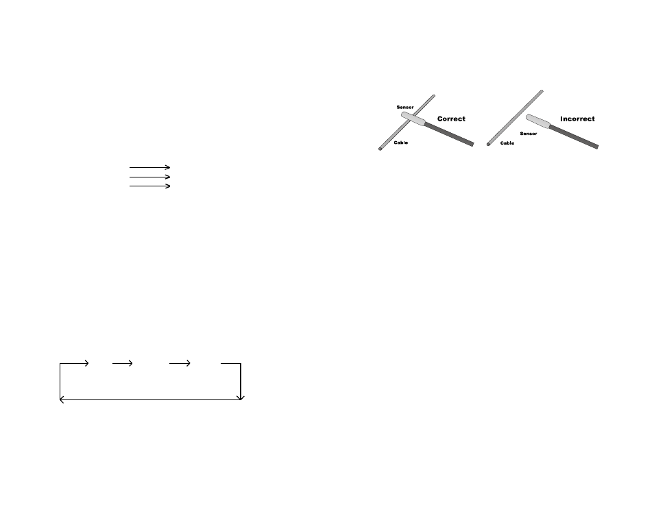
5 - How to use the probe:
The probe of the FF310R is built of coiled steel and can be bent as needed, in order to
reach wires in congested or difficult areas. Depending on the circuit characteristics and
the sensitivity setting, the probe will pick-up the signal from the wire in a wide range of
positions . However for the best possible range the FF310R’s probe tip (yellow cap) should
be positioned perpendicular ( at 90°) to the wire being traced and either above or below
it, as shown in Fig. 1 below.
Fig. 1 - Probe positioning
6 - Locating Short Circuits
Refer to the Hook Up Reference Chart in Page 6.
6.1 Observe the limits and safety precautions at all times (refer to the beginning of
this handbook).
6.2 Connect the FF310T (transmitter) in series with the short-circuited wire, making sure
one of the unit’s clips is connected to the circuit’s positive supply (or vice versa for
vehicles with positive supply connected to chassis). A fuse socket connector (in place of
the blown fuse), a connector, etc., provides a convenient hook-up as shown in Fig. 2 and
Fig. 3 in Page 6.
6.3 Switch the transmitter on by pressing the On/Off button and observe if the Red LED
on the FF310T starts flashing. If not check connections, power supply, and in the
case of having connected the unit to any place other than the fuse socket, check
that the circuit’s fuse is installed and in working condition (not open). If necessary
replace with a new fuse with the same ratings.
6.4 Switch the FF310R (tracer) on, and if green LED is turn on.
6.5 Verify that the FF310R is set to the low sensitivity level (single green
LED Flash).
6.6 Slowly sweep the wire, conduit, etc., with tracer, ensuring the tracer’s probe is
perpendicular and above or below the wire being traced and as close as
possible to it .
6.7 Follow the wire or check it at different points, starting from the transmitter and moving
towards the load (accessory, light , etc.) observing the positioning of the probe as
indicated above. Continue this procedure while the audio signal (beeping sound) and
visual signal (flashing Red LED light) indicates the integrity of the circuit. If beeping
and flashing slows down or stops it indicates that the probe is either moving away
from the faulty wire or it has passed beyond the short circuit point.
6.8 If difficult or impossible to get the FF310R Tracer to pick-up any signal, then adjust
the sensitivity to HIGH, and check again if a signal is received.
6.9 Double check positioning the probe before and after the suspected place. If the short
circuit point has been found, the audio/visual indicators will show circuit integrity on
for one position, but not for the other.