Rpm (r-1) – Electronics International R-1-N1 User Manual
Page 12
RPM (R-1)
RPM (R-1)
RPM (R-1)
RPM (R-1)
RPM (R-1)
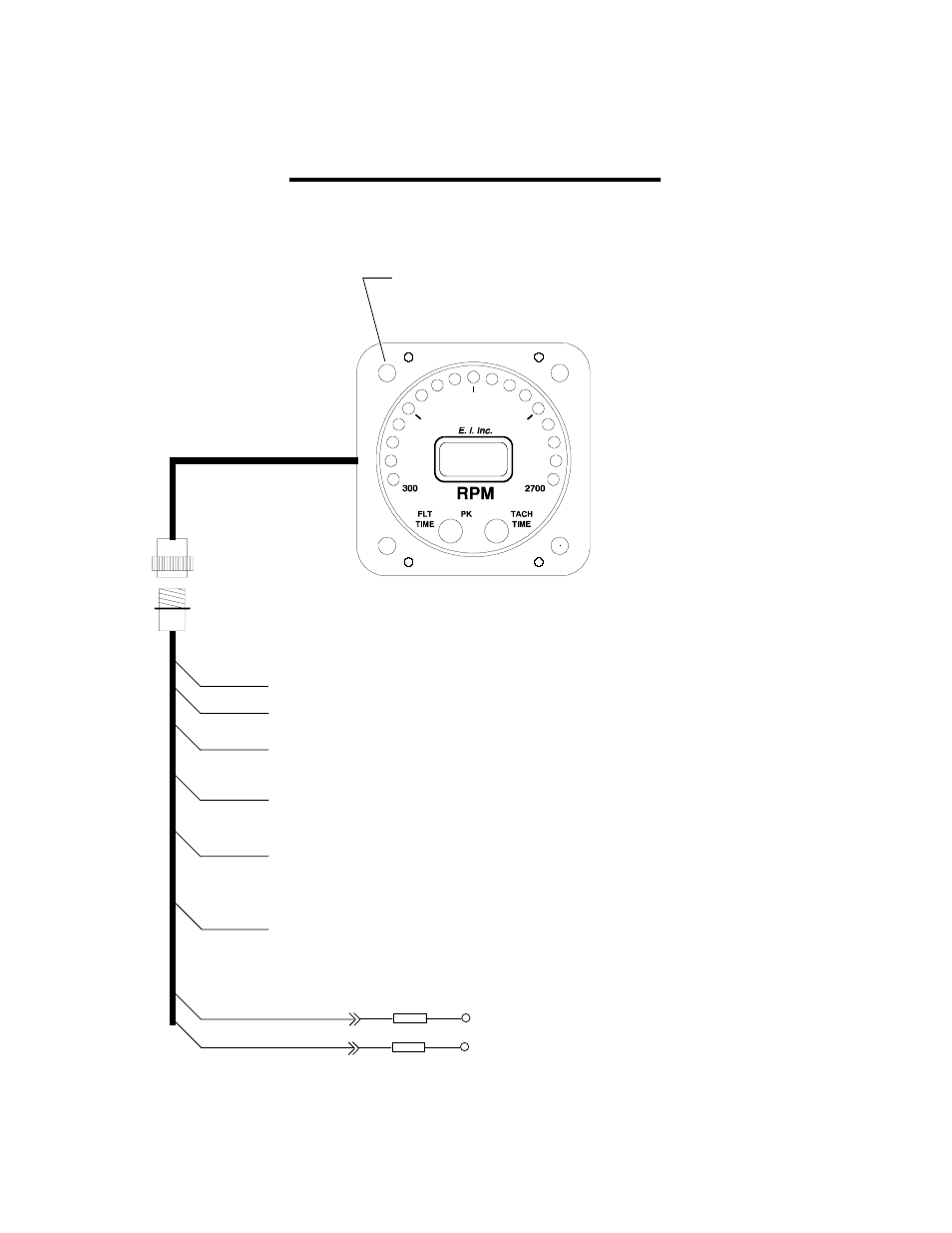
Wiring Diagram
Wiring Diagram
Wiring Diagram
Wiring Diagram
Wiring Diagram
Brown
10
WD 0311911
Do not use screws longer
than 1/2" (4 ea.).
Analog LED Lighting Control Line, connects to Panel Light Rheostat. 12/24
volts dims the analog LEDs.
External Warning Control Line. Can be connected to a relay to control an
external light, buzzer, etc. Grounds when Red Warning Light is on. Current
must be limited to 1/10 amp maximum.
24V Backlight Control Line, connects to Red Power Lead for a 24V system via
the power fuse. Connect to ground for 12 Volt System.
Connect to ground for 12 Volt System.
Connect to ground for 12 Volt System.
Connect to ground for 12 Volt System.
Connect to ground for 12 Volt System.
12V Backlight Control Line, connects to Red Power Lead for a 12V system via
the power fuse. 12 volts turns on the digital display backlight.
Ground Lead, connects to Ground.
Power Lead, connects to 12 or 24 Volt Bus via one amp fuse.
White/Yel
Black
Red
White/Brwn
White/Red
White/Orng
Orange
Circular Connector
To Left or Right Mag Lead.
To the Other Mag Lead.
Isolator
Isolator
Wire Harness
Rev. A: 6/16/92