Bodyline Products International AXIS ORBIT AX-2320 User Manual
Page 13
Axis Orbit 4000 and Orbit 2000 |24| english
Axis Orbit 4000 and Orbit 2000 |2| english
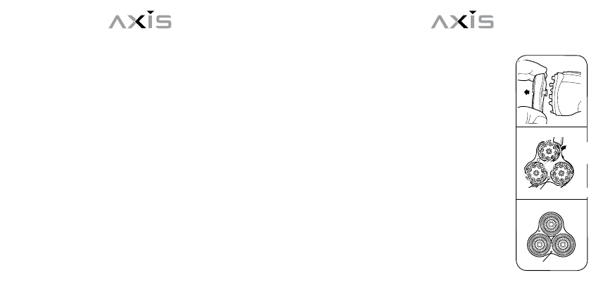
1. Grasp the floating head assembly and gently lift it off from the
shaver. (fig.1, part 1)
2. Detach the inner cutter assembly (fig. 2, part 2) by pushing down
and turning counter clockwise the screw knob in the center (fig. 2, part
3), then pull upwards away from the outer cutter assembly.
3. Then, remove outer cutter assembly. (fig. 3, part 4)
To replace floating heads and inner cutter as-
sembly
1. First, insert the new outer cutter assembly into the frame, then insert
the new inner cutter assembly back into the housing and lock in place
by pushing down and turning clockwise the screw knob located in the
center. Please make sure that the frame pins (see fig. 3, part 5) are
lined up with the locating holes as seen in fig. 2, part 6.
2. Please make sure that the floating head and inner cutter assembly
is secure before attaching floating head and inner
cutter assembly to shaver.
3. When locking assembly back into place, a
small click will be heard.
4. Always keep protective head guard attached
when shaver is not in use. This will assure that
the floating heads will not be damaged.
Ordering replacement parts
Please contact Axis/BPI at 1-877-263-9500
to order replacement parts for your Axis shaver.
Please refer to the following part number.
Part number: AO-1
Description: Replacement Rotary
Heads and Rotary Blades Assembly for Model
2
1
4
5
3
6
inner cut assembly
screw
knob
locating holes
outer cut assembly
frame pins