Perma pure llc – Perma Pure Baldwin-Series M5 User Manual
Page 4
PERMA PURE LLC
Model M5 User’s Manual
Doc. #580: Revision: 000
Page 4 of 22
General description
The Perma Pure/Baldwin Tester’s Choice Model M5 Thermo-Electric cooler features a complete gas
conditioning system in one easy to manage enclosure. The unique design leaves additional space to
install or access other sample conditioning system components. A unique drop-down door on the
M5 cooler section, provides easy access to electronic boards and the power supply. All electronic
boards (control, relay, and display) are mounted on the door of the cooler for easy access. Sample
pump and peristaltic drain pump(s) are also mounted within the enclosure.
The process of sampling combustion
product stack gas or exhaust from internal
combustion engines requires a method to
remove the moisture from the sample,
without removing the gas components of
interest. The Tester’s Choice M5 System is
an ideal way to decrease the dew point of
combustion gases to a repeatable, stable,
constant low dew point. The Tester’s Choice
M5 system prevents water condensation in
sample pre-filters, sample pumps, and gas
analyzers. For gas analyzers where water
vapor is an interferent, a stable, repeatable,
dew point, becomes a part of the gas
analyzer performance specification. The
Tester’s Choice system provides this
constant low water concentration, resulting
in an accurate component gas
measurement.
The Tester’s Choice M5 system removes the moisture from the sample gas by cooling the gas as it
passes through a laminar impinger (heat exchanger). A diagram showing the gas flow path through
an impinger is shown in the Appendix B2. The impinger, made of 316L stainless steel, Durinert
®
(a
corrosion-resistant inert coating over 316L stainless steel), PVDF (Kynar®), or glass, is mounted
within a thermally insulated heat transfer block bored to receive the impinger without a mechanical
lock. This assembly allows the easy removal of any impinger simply by slipping it out of the cooling
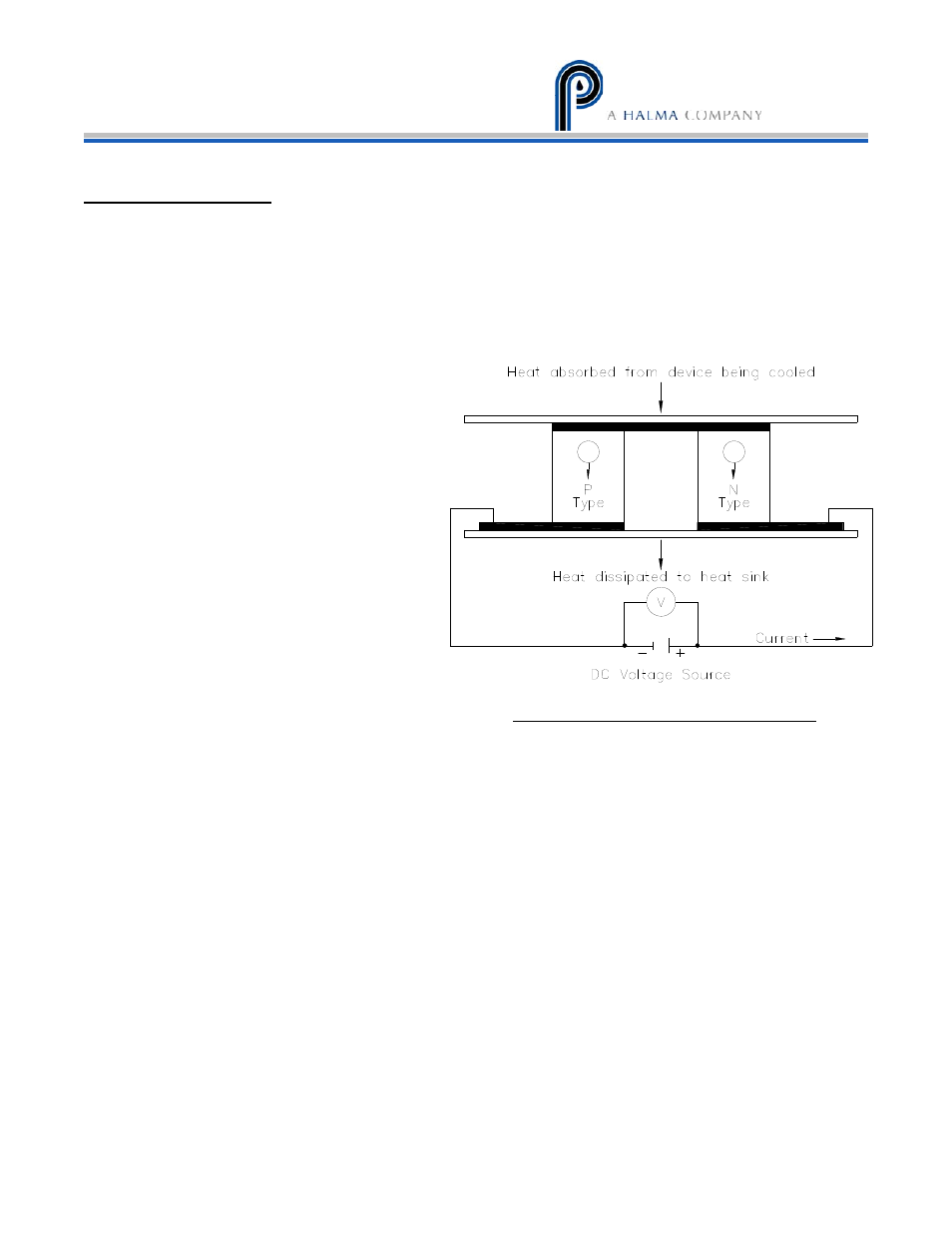
block by hand. The heat transfer block cools the heat exchanger through the heat pumping action
of the Peltier element. The heat transfer block is on the cold side of the thermo-electric element
and the heat sink is on the hot side of the thermo-electric element. The desired temperature is
maintained by a closed loop control system, which is implemented through an analog proportional
controller. The controller uses a type K thermocouple as a sensor.
Figure 1: Thermo-electric element (Peltier)