Theory of operation – MotorVac COOLANTCLEAN-1000 User Manual
Page 8
Theory of Operation
Detailed descriptions of the various operations, valves and indicators that make up the
COOLANTCLEAN 1000’s control panel are listed below.
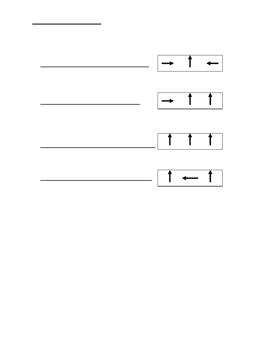
3- Control valves:
♦ When the valves are in the VACUUM position .
(And unit connected to a vehicle) The unit will apply vacuum thru the “Green” hose when the air
control valve is turned on and the regulator is adjusted to adequate pressure.
♦ When the valves are in the HOLD position:
After maximum vacuum has been achieved (24 inch’s of vacuum/ top hose collapsed) you can
turn the #3 valve to the ‘HOLD” position. This allows for system leak tests after repairs have been
completed on a vehicle.
♦ When the valves are in the FILL-CLEAN position:
The unit will pump New coolant from the clean fluid tank out of the “Green” hose.
♦ When the valves are in the FILL-USED position:
The unit will pump used fluid from the used/waste fluid tank out of the ”Green” hose. Used to refill
an engine with used fluid after an engine repair has been completed or to empty the waste fluid
into a recycle tank.