Gas pressure regulator – A.O. Smith BTI 120 User Manual
Page 12
12
MALFUNCTION OF THE SUPPLY SYSTEM, THE GAS VALVE
MUST BE CHECKED FOR SAFE OPERATION. MAKE SURE
THAT THE OUTSIDE VENTS ON THE SUPPLY REGULATORS
AND THE SAFETY VENT VALVES ARE PROTECTED AGAINST
BLOCKAGE. THESE ARE PARTS OF THE GAS SUPPLY SYSTEM,
NOT THE HEATER. VENT BLOCKAGE MAY OCCUR DURING
ICE STORMS.
TABLE 6 - GAS SUPPLY LINE SIZES (IN INCHES)*
MAXIMUM CAPACITY OF PIPE IN
CUBIC FEET PER HOUR
LENGTH
NOMINAL IRON PIPE SIZES (INCHES)
IN
FEET
1/2" 3/4" 1" 1 1/4" 1 1/2"
2"
2 1/2"
3"
4"
10
175 360 680 1400 2100 3960
6300
11000 23000
20
120 250 465 950
1460 2750
4360
7700 15800
30
97
200 375 770
1180 2200
3520
6250 12800
40
82
170 320 660
990
1900
3000
5300 10900
50
73
151 285 580
900
1680
2650
4750
9700
60
66
138 260 530
810
1520
2400
4300
8800
70
61
125 240 490
750
1400
2250
3900
8100
80
57
118 220 460
690
1300
2050
3700
7500
90
53
110 205 430
650
1220
1950
3450
7200
100
50
103 195 400
620
1150
1850
3250
6700
125
44
93
175 360
550
1020
1650
2950
6000
150
40
84
160 325
500
950
1500
2650
5500
175
37
77
145 300
460
850
1370
2450
5000
200
35
72
135 280
430
800
1280
2280
4600
IT IS IMPORTANT TO GUARD AGAINST GAS VALVE FOULING
FROM CONTAMINANTS IN THE GAS WAYS. SUCH FOULING
MAY CAUSE IMPROPER OPERATION, FIRE OR EXPLOSION.
IF COPPER SUPPLY LINES ARE USED THEY MUST BE
INTERNALLY TINNED AND CERTIFIED FOR GAS SERVICE.
BEFORE ATTACHING THE GAS LINE, BE SURE THAT ALL GAS
PIPE IS CLEAN ON THE INSIDE.
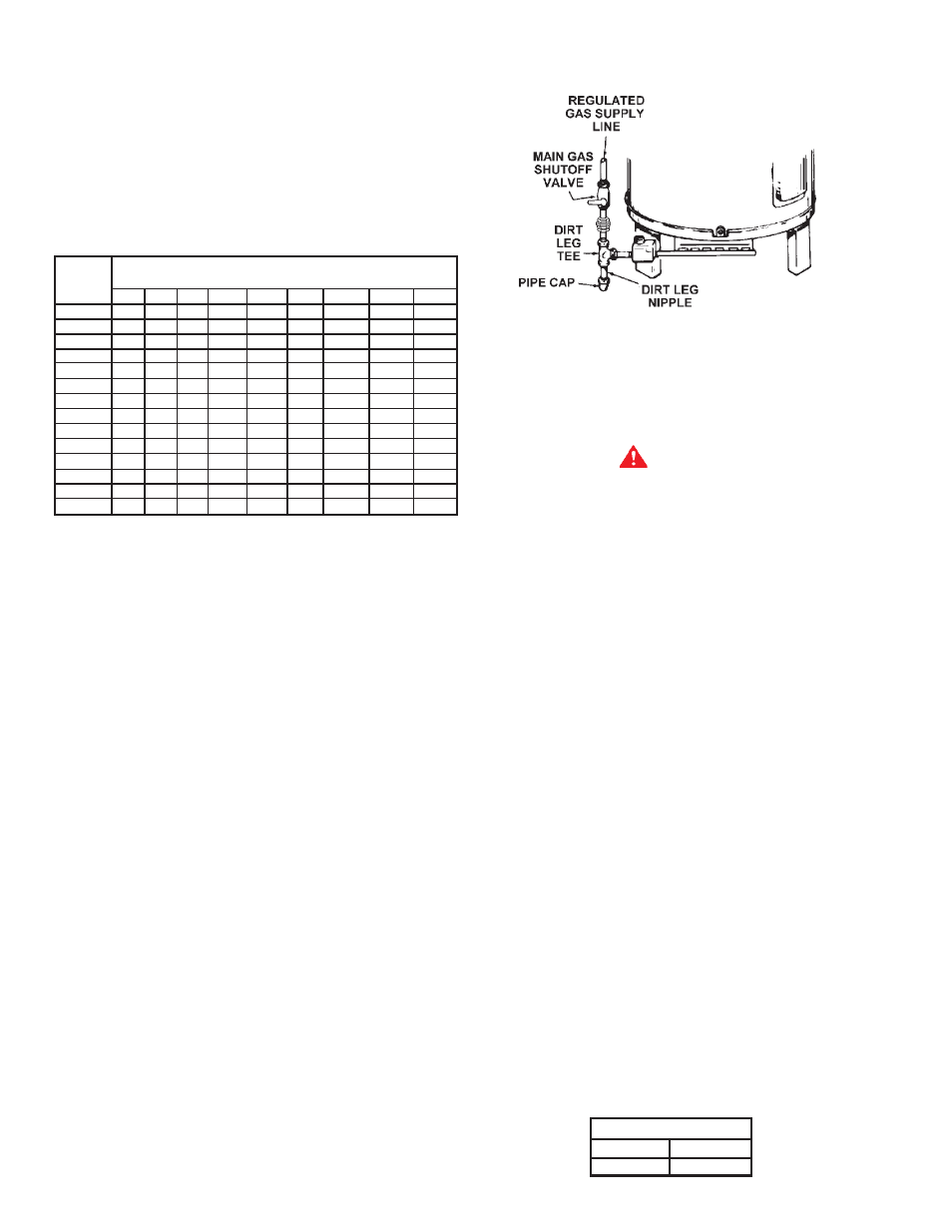
TO TRAP ANY DIRT OR FOREIGN MATERIAL IN THE GAS
SUPPLY LINE, A DIRT LEG (SOMETIMES CALLED SEDIMENT
TRAP OR DRIP LEG) MUST BE INCORPORATED IN THE PIPING
(SEE FIG. 8). THE DIRT LEG MUST BE READILY ACCESSIBLE
AND NOT SUBJECT TO FREEZING CONDITIONS. INSTALL IN
ACCORDANCE WITH RECOMMENDATIONS OF SERVING GAS
SUPPLIERS. REFER TO THE LATEST VERSION OF THE
NATIONAL FUEL GAS CODE.
To prevent damage, care must be taken not to apply too much
torque when attaching gas supply pipe to gas valve inlet.
Apply joint compounds (pipe dope) sparingly and only to the
male threads of pipe joints. Do not apply compounds to the first
two threads. Use compounds resistant to the action of liquefied
petroleum gases.
BEFORE PLACING THE HEATER IN OPERATION, CHECK FOR
GAS LEAKAGE.
Use soap and water solution or other material
acceptable for the purpose in locating the leaks.
DO NOT USE
MATCHES, CANDLES, FLAME OR OTHER SOURCES OF
IGNITION FOR THIS PURPOSE.
DISCONNECT THE HEATER AND ITS MANUAL GAS SHUTOFF
VALVE FROM THE GAS SUPPLY PIPING SYSTEM DURING ANY
SUPPLY PRESSURE TESTING EXCEEDING 1/2 PSIG. GAS
SUPPLY LINE MUST BE CAPPED WHEN DISCONNECTED
FROM THE HEATER FOR TEST PRESSURES OF 1/2 PSIG OR
LESS. THE APPLIANCE NEED NOT BE DISCONNECTED, BUT
MUST BE ISOLATED FROM THE SUPPLY PRESSURE TEST BY
CLOSING THE MANUAL GAS SHUTOFF VALVE.
GAS PIPING AND DIRT LEG INSTALLATION
FIGURE 9
PURGING
Gas line purging is required with new piping or systems in which
air has entered.
CAUTION
PURGING SHOULD BE PERFORMED BY PERSONS
EXPERIENCED IN THIS TYPE GAS SERVICE. TO AVOID RISK
OF FIRE OR EXPLOSION, PURGE DISCHARGE MUST NOT
ENTER CONFINED AREAS OR SPACES WHERE IGNITION CAN
OCCUR. THE AREA MUST BE WELL VENTILATED AND ALL
SOURCES OF IGNITION MUST BE INACTIVATED OR REMOVED.
GAS METER SIZE — NATURAL GASES ONLY
Be sure the gas meter has sufficient capacity to supply the full
rated gas input of the water heater as well as the requirements
of all other gas fired equipment supplied by the meter. If gas
meter is too small, ask the gas company to install a larger meter
having adequate capacity.
GAS PRESSURE REGULATOR
The gas pressure regulator is built into the gas valve and is
equipped to operate on the gas specified on model and rating
plate. The regulator is factory adjusted to deliver gas to burner at
correct water column pressure allowing for a nominal pressure
drop through the controls.
The minimum gas supply pressure for input adjustment must
not be less than 4.5" w.c. for natural gas.
Do not subject the combination gas valve to inlet gas pressures
of more than 14.0" W.C. - natural gas. A service regulator is
necessary if higher gas pressures are encountered.
Gas pressure specified in Table 7, refer to flow pressure taken
at pressure tap of automatic gas valve while heater is operating.
TABLE 7
MANIFOLD GAS PRESSURE IN INCHES
OF WATER COLUMN (ALL MODELS*)
TYPE OF GAS
Natural
Propane
3.5
10.0