Mach III Clutch X6J2G-STH User Manual
Page 3
7/9/2013
CLUTCHBR_SHAFT_DBLSPKT_MANUAL
Page 3 of 4
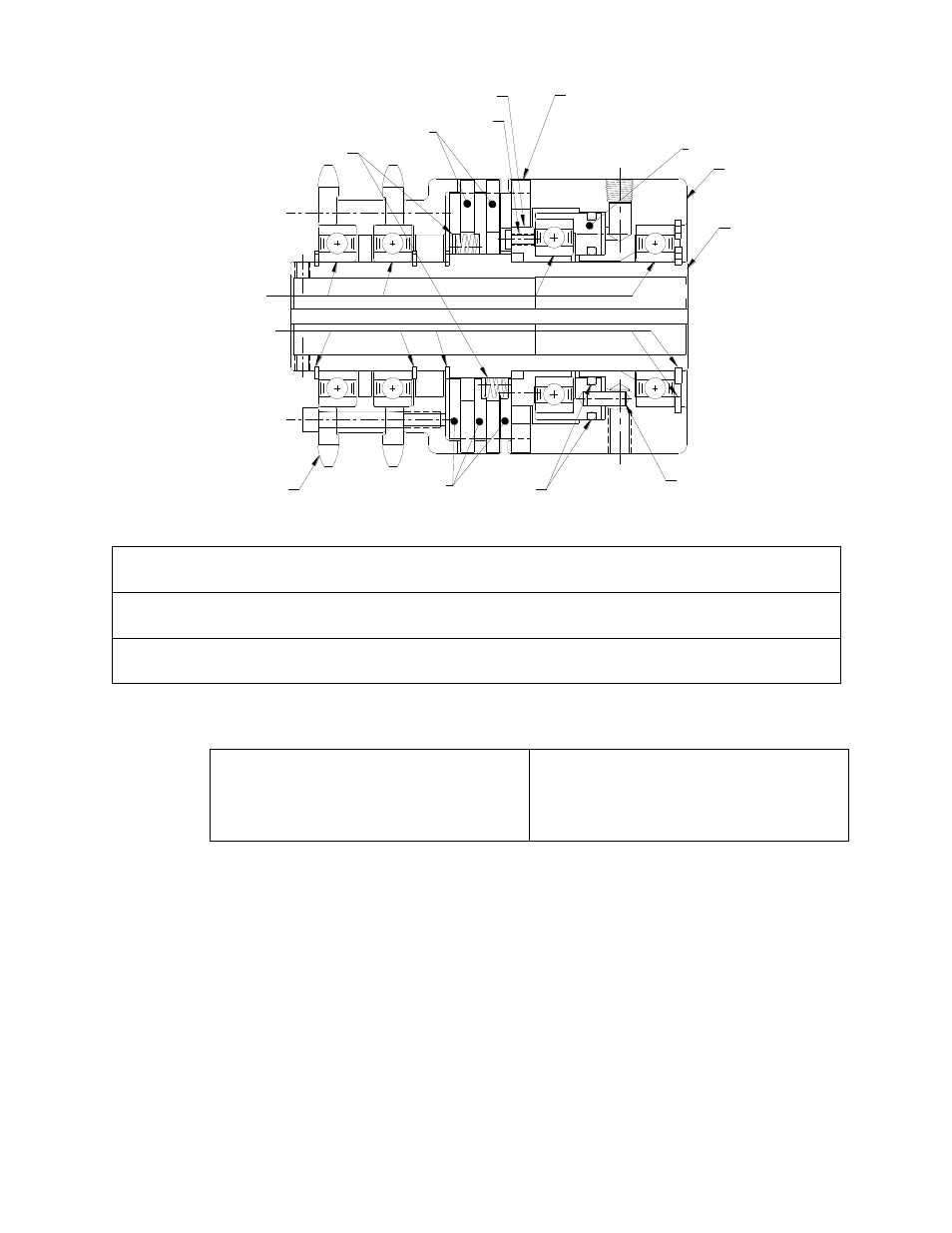
BEARING
RETAINER RING
O-RING
DRIVE DISC
PIN
SCREW
SPROCKET/SLEEVE
SUB ASSEMBLY
PISTON
CONE
CYLINDER
DRIVE HUB
BRAKE FRICTION
DISC
SPRING
FRICTION DISC
V.
Parts diagram
Repair Kit:
Part number = Clutch-Brake
Product Number + “-RPRK” (e.g. X3D2H-STH-
RPRK).
Additional
Parts:
Contact Mach III to obtain a complete listing of additional parts kits available for
your specific clutch. Please reference product number when calling or e-mailing.
Repair
services:
Factory repair is available. A return materials authorization (RMA) number must
be obtained prior to sending any unit in for repair.
VI.
Repair Kit Installation Procedure
Tools Required
Hex Wrench Set
Rubber Mallet or similar soft face hammer
Retainer (snap) Ring Pliers
Scraper
Compounds Required
Grease
O-ring Lubricant
Loctite
®
#609 Retaining Compound
Anti-Seize Lubricant (for re-installation)
A. CLUTCH & BRAKE FRICTION DISC & SPRING REPLACEMENT
(1)
Remove clutch-brake from shaft and place in vertical position with sleeve end facing
upward.
(2)
Remove retainer ring.
(3)
Remove sprocket/sleeve sub-assembly from drive hub. The sub-
assembly’s bearings
are a slide fit on the drive hub and are affixed to the drive hub with a thin coating of
Loctite
®.
You may need to strike the hub, or an object inserted in the hub with a rubber
mallet or similar soft face hammer, while pulling the sleeve upwards to break the
Loctite
®
seal.
(4)
Two remaining retainer rings should now be accessible. Remove the first retainer ring.
(5)
The last retainer ring is under pressure from the springs. It may be necessary to
use an arbor press to compress the springs to remove this last retainer ring.
(6)
Remove the drive discs, springs and friction discs.