Important, Reference diagram, I. installation – Mach III Clutch 118PI & 118PI-ULOW User Manual
Page 2
7/10/2013
CLUTCH_SENSIFLEX_PI_MANUAL
Page 2 of 5
**IMPORTANT**
The gap between the friction and drive surface is factory set between 0.010 and 0.020 Inch.
This is the ideal clearance for proper performance.
Increasing this gap may result in air leaks and damage to the diaphragm actuator.
Decreasing this gap prevents full disengagement of the clutch.
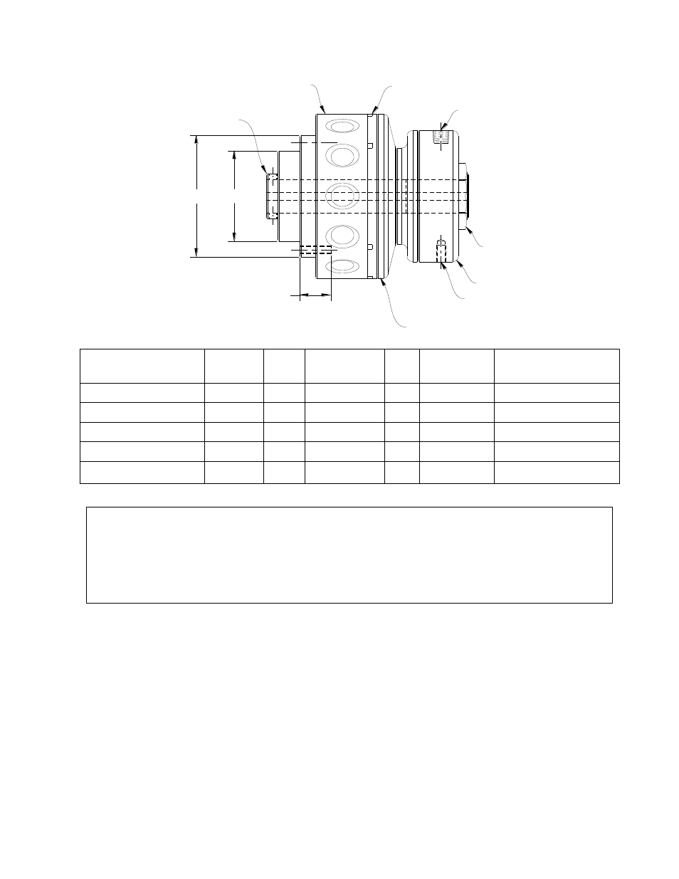
H
BC
E
AIR INLET
FRICTION LINING
SLEEVE - INPUT MEMBER
DRIVE HUB - OUTPUT MEMBER
ADJUSTMENT NUT
AIR CYLINDER
PISTON/DRIVE DISC
ASSEMBLY
INPUT FOR REACTION ARM
Reference Diagram:
I.
Installation
A. SHAFT PREPARATION & MOUNTING
Mach III Clutch products are bored to fit a precision plug gauge for the specified bore size
and should slide-fit your shaft. Make certain that the shaft is free of burrs or nicks. It
may be necessary to file or sand the shaft to assure a slide fit. Never hammer the clutch
onto the shaft. Hammering on the clutch may cause evident damage or subtle injury that
will shorten the wear life of the unit, and will void the warranty. Apply the anti-seize (E-Z
Break®) lubricant from the packet provided, or equivalent, to the shaft. Slide the clutch
over the key on the shaft, align the pulley or sprocket and tighten the set screws.
Product#
H
E
X
BC
Air Inlet
Reaction Arm Input
38PI/38PI-ULOW
1.875
0.61
(3) 10 - 24
2.25
1/16" NPT
10 - 24
58PI/58PI-ULOW
2.749
0.87
(3) 1/4 - 20
3.25
1/8" NPT
1/4 - 20
78PI/78PI-ULOW
3.875
1.20
(3) 5/16 - 18
4.50
1/8" NPT
1/4 - 20
98PI/98PI-ULOW
5.000
1.25
(6) 3/8 - 16
5.63
1/8" NPT
1/4 - 20
118PI/118PI-ULOW
6.250
1.50
(6) 7/16 - 14
7.00
1/4" NPT
5/16 - 18