Mach III Clutch M6G2G-STH & M6G2G-STL User Manual
Page 3
7/9/2013
CLUTCH_MECH_W_COUPL_AIR_RD_MANUAL
Page 3 of 4
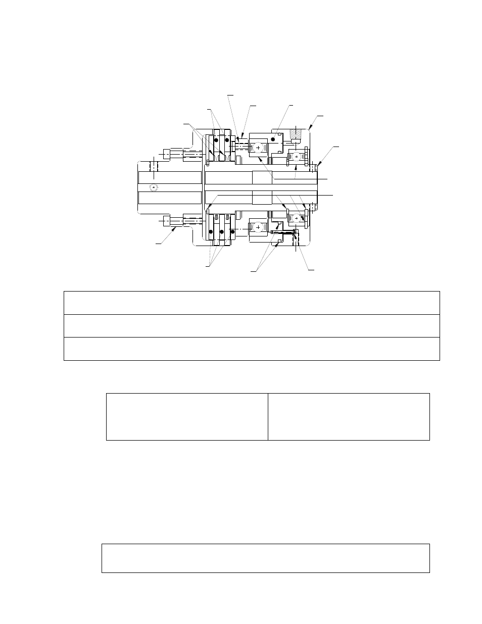
O-RING
DRIVE DISC
SPRING
PIN
SCREW
COUPLING
PISTON
FRICTION DISC
CONE
CYLINDER
DRIVE HUB
BEARING
RETAINER RING
IV.
Routine Maintenance
When installed and operated according to the preceding guidelines, Mach III Clutch
products should require little or no routine maintenance. A repair kit is available which
contains all parts subject to typical wear: friction discs, springs and O-rings.
V.
Parts diagram
Repair Kit:
Part number = Clutch Product Number + “-RPRK” (e.g. M3G2R-STH-RPRK)
Additional
Parts:
Contact Mach III to obtain a complete listing of additional parts kits available for
your specific clutch. Please reference product number when calling or e-mailing.
Repair
services:
Factory repair is available. A return materials authorization (RMA) number must
be obtained prior to sending any unit in for repair
VI.
Repair Kit Installation Procedure
Tools Required
Hex Wrench Set
Rubber Mallet or similar soft face hammer
Retainer (snap) Ring Pliers
Scraper
Compounds Required
Grease
O-ring Lubricant
Loctite
®
#609 Retaining Compound
Anti-Seize Lubricant (for re-installation)
A. FRICTION DISC & SPRING REPLACEMENT
(1)
Remove clutch from shaft and place in vertical position with drive disc end facing
upward.
(2)
Remove retainer ring, drive discs, springs and friction discs.
(3)
Drive discs should be clean, dry and free of burrs or nicks.
(4)
Reassemble drive & friction disc section according to reference drawing using new
friction discs, springs and steel drive discs as necessary.
(5)
Assure that drive discs move freely on the drive hub and that the lugs of the friction
discs move freely in the drive slots of the adapter.
Note Regarding Wave Spring Alignment:
The beginning of the coil of each spring should be placed in the same relative (O-Clock)
position to the drive hub to assure equal separation of the drive disc.