Reference diagram, I. installation, Important – Mach III Clutch 98BK & 98BK-ULOW User Manual
Page 2
7/10/2013
BRAKES_SENSIFLEX_BK_MANUAL
Page 2 of 5
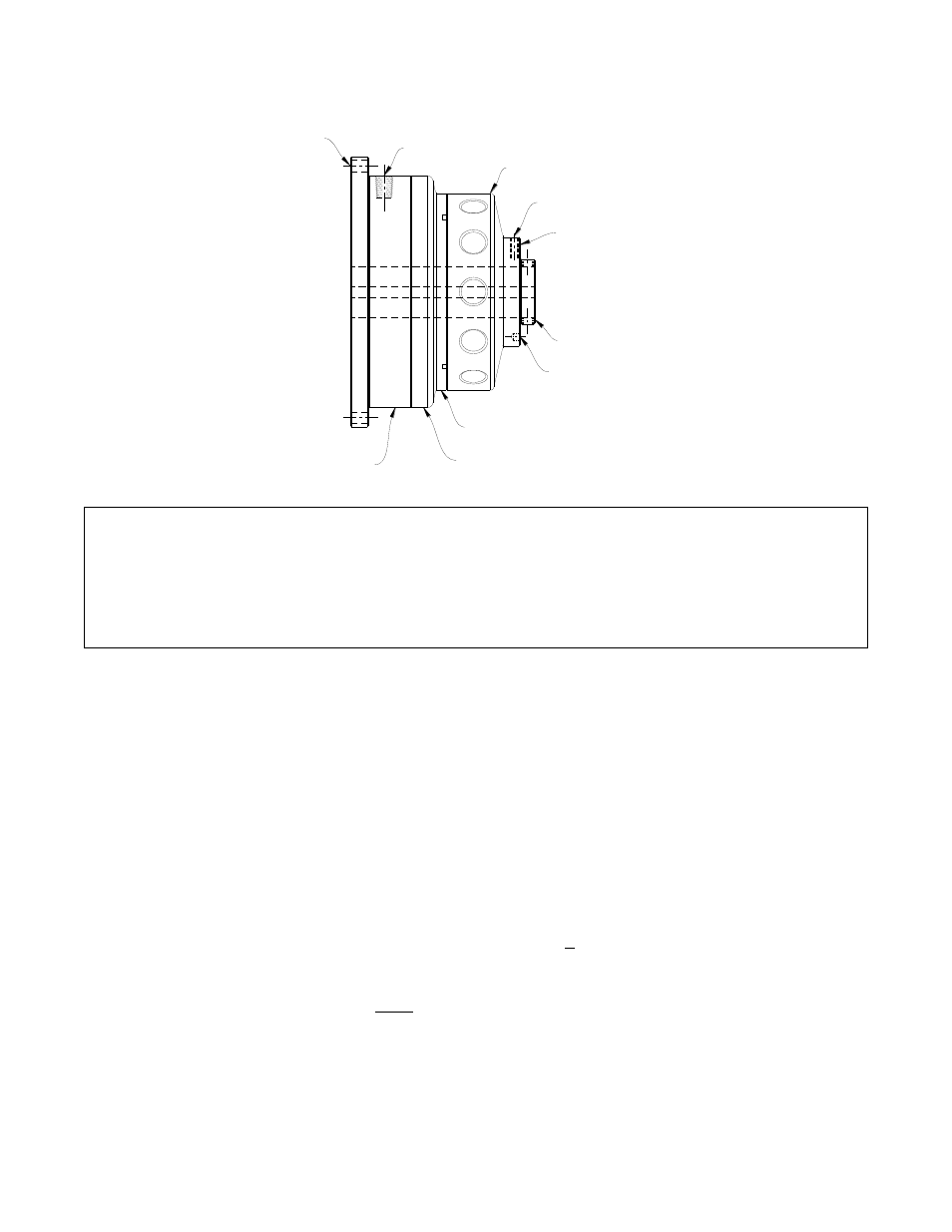
MOUNTING
HOLES
AIR INLET
DRIVE DISC
NYLON PT.
SET SCREW
NUT
DRIVE HUB
SPANNER HOLES
FRICTION DISC
PISTON
CYLINDER
Reference Diagram:
I.
Installation
A. SHAFT PREPARATION & MOUNTING
Mach III Clutch products are bored to fit a precision plug gauge for the specified bore size
and should slide-fit your shaft. Make certain that the shaft is free of burrs or nicks. It may
be necessary to file or sand the shaft to assure a slide fit. Never hammer the brake onto
the shaft. Hammering on the brake may cause evident damage or subtle injury that will
shorten the wear life of the unit, and will void the warranty.
1. Apply the anti-seize (E-Z Break) ® lubricant from the packet provided, or equivalent, to
the shaft.
2. Slide the brake over the key on the shaft and tighten the set screws.
3. If the surface that the brake is to be mounted to is absolutely perpendicular to the
shaft, use the four (4) flange mounting holes of the brake to insert bolts and tighten to
the machine.
4. If the mounting plate is not perfectly perpendicular to the shaft, it is recommended
that the brake be mounted using shoulder bolts to allow the brake housing to float. If
the brake is mounted with strain on the bearing, premature bearing failure is likely to
occur.
**IMPORTANT**
The gap between the friction and drive surface is factory set between 0.010 and 0.020 Inch.
This is the ideal clearance for proper performance.
Increasing this gap may result in air leaks and damage to the diaphragm actuator.
Decreasing this gap prevents full disengagement of the brake.