Lightronics IDW112 User Manual
Page 2
Page
2
of
4
IDW-112 DMX OPTICAL ISOLATOR
Version 0.2 OWNERS MANUAL
08/09/2012
www.lightronics.com
20090526
drp
Lightronics
Inc.
509
Central
Drive
Virginia
Beach,
Va
234354
757
486
3588
INSTALLATION
REMOVE ALL POWER FROM THE UNIT BEFORE
MAKING OR CHANGING ANY CONNECTIONS
POWER SUPPLY
The IDW-112 operates from 120 VAC, 60Hz power
and has a 1/4 Amp fuse. Power should be connected to
the 3 pole terminal strip as shown in the diagram
IDW-
112 FACE VIEW.
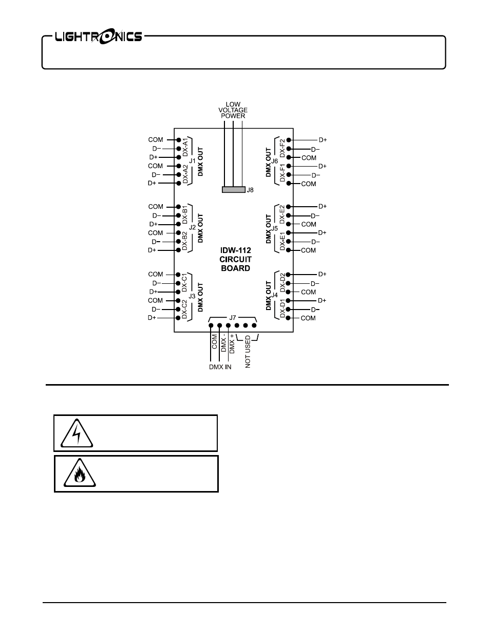
SIGNAL CONNECTIONS
All DMX input and output connections are made
directly on the circuit board.
Six connectors with screw down terminals are
provided. There are two DMX output signals on each
connector. Each DMX output signal consists of 3
connector terminals (COM, D-, D+). The diagram
IDW-112 INTERNAL CIRCUIT BOARD
above shows
all signal connections.
OPERATION
Operation is automatic when power is applied and a
DMX input signal is connected.
The circuit board contains a
RED
LED power indicator
which is on when power is applied.
IDW-112 INTERNAL CIRCUIT BOARD
WARNING
RISK OF ELECTRIC SHOCK
WARNING
RISK OF FIRE