Fl-4020 fluorescent ballast controller – Lightronics FL2020D User Manual
Page 4
Page 4 of 5
FL-4020 FLUORESCENT BALLAST CONTROLLER
Version 1.0
OWNERS MANUAL
10/06/2005
www.lightronics.com
Lightronics Inc
509 Central Drive Virginia Beach, VA 23454
Tel 757 486 3588
INSTALLATION NOTES
1. Chassis is 18”H x 15”W x 4.25” D. Mulitple knockouts are provided at top and bottom for wiring access.
2. The unit weighs aprox. 10 pounds.
3. Mounting holes are provided at rear of box. Box should be spaced aprox. 1” from wall.
4. A 12 ft wiring harness (with connector) is provided to connect to an AR-1202 dimmer.
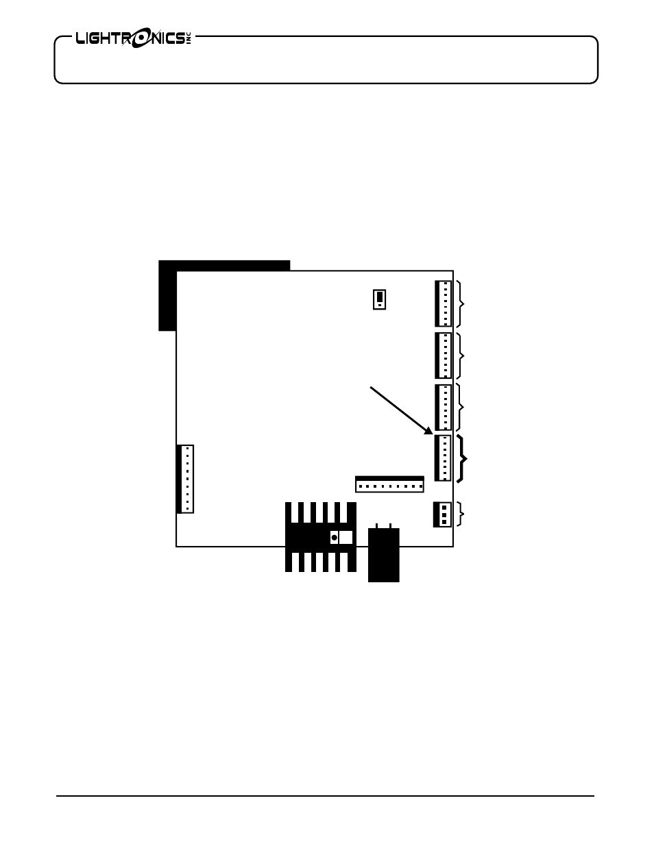
FL-4020 CONTROL SIGNAL CONNECTIONS AT AR-1202
The 8 conductor cable which supplies the control inputs to the FL-4020 is supplied with a connector at the AR-
1202 end. This cable connects directly to J7 on the circuit board located on the AR-1202 door. The location of
J7 is shown in the diagram below.
3 PH
1 PH
POWER
INPUT
AR-1202
CIRCUIT BOARD
ASSY
(REAR VIEW SHOWN)
CHAN
1 - 4
CHAN
5 - 8
CHAN
9 - 12
12 VAC
CHAN
13 - 16
TO
FL-4020
1
2
3
4
5
6
7
8
J7
OWNER MAINTENANCE
There is a 1/2 Amp., 250 Volt, fast acting fuse in the unit to protect the internal electronic circuits from an
overvoltage condition. The fuse may be replaced ONLY by a fuse of the same size and type.
The best way to prolong the life of your unit is to keep is cool, clean, and dry. It is important that the cooling
intake and exit vent holes are clean and unobstructed.
Service by other than Lightronics authorized agents may void your warranty.
OPERATING AND MAINTENANCE ASSISTANCE
If service is required, contact the dealer from whom you purchased the equipment or contact Lightronics, Service
Department, 509 Central Drive, Virginia Beach, VA 23454 TEL 757 486 3588