Maintenance, Troubleshooting, Optical sensor – Liquid Controls Optical Air Eliminator US Patent 7000628 Refined Fuels Applications A8981 & A8981A User Manual
Page 14: Warning
14
Maintenance
Troubleshooting
PROBLEM
Excessive liquid flowing out of vent to spit tank.
Scenario 1: Solenoid not closing.
• Check S3 solenoid wiring.
• Measure resistance across S3 solenoid. Value should
read approximately 15 ω. If not, replace S3 sole-
noid.
• Inspect S3 solenoid for blockage. Refer to disassem-
bly instructions.
• LectroCount CPU failure. Replace CPU board.
Scenario 2: Optical Sensor not functioning.
• Check optical sensor wiring.
• Measure resistance between the RED and WHITE
wires. Value should be approximately 10kω. If not,
replace optical sensor.
• LectroCount CPU failure. Replace CPU board.
PROBLEM
No liquid flowing through meter during delivery.
Scenario 1: Liquid level not rising in optical air elimi-
nator.
• Check S3 solenoid. It may not be opening to allow
air/vapor to vent.
• Check S3 solenoid wiring.
• Measure resistance across S3 solenoid. Value should
read approximately 15 ω. If not, replace S3 sole-
noid.
• Inspect S3 solenoid for blockage. Refer to disassem-
bly instructions.
• LectroCount CPU failure. Replace CPU board.
Scenario 2: Meter outlet valve not opening
• Check wiring of the outlet valve S1 solenoid.
• Measure resistance across S1 solenoid. Value
should read approximately 15ω. If not, replace S1
solenoid.
• Inspect S1 solenoid for blockage. Refer to the manual
which accompanies the valve.
• LectroCount CPU failure. Replace CPU board.
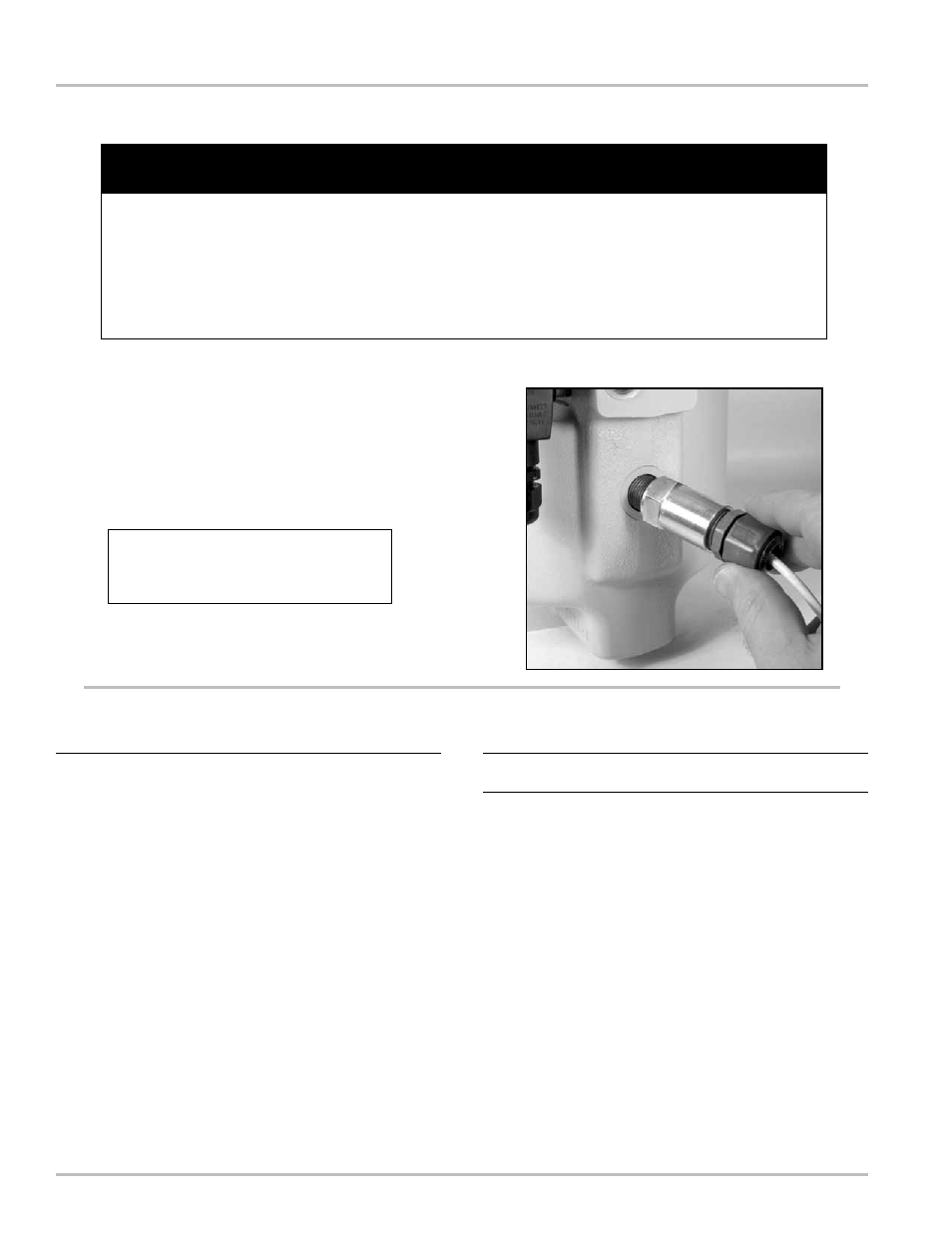
Optical Sensor
If the optical sensor ever needs replacement, use a 1”
open end wrench to remove the optical sensor from the
housing. When installing a new optical sensor, care should
be taken not to exceed a torque of 75 in-lbs (8.5 Nm).
Excessive torque may damage the sensor.
!
WARNING
Before disassembly of any meter or accessory component,
ALL INTERNAL PRESSURES MUST BE RELIEVED
AND ALL LIQUID DRAINED FROM THE SYSTEM IN ACCORDANCE WITH ALL APPLICABLE PROCEDURES.
Pressure must be 0 (zero) psi. Close all liquid and vapor lines between the meter and liquid source.
Failure to follow this warning could result in property damage, personal injury, or death from fire and/or explosion, or
other hazards that may be associated with this type of equipment.
A light coating of grease or anti-seize
lubricant should be applied to the threads
of the sensor prior to assembly.