Headphone jack (fig. 1), Mono plug/stereo plug usage, Audio level – Lectrosonics R5a User Manual
Page 6: Frequency adjust (fig. 2), Figure 2 - frequency adjustment, Figure 3 - r5a block diagram
R5a
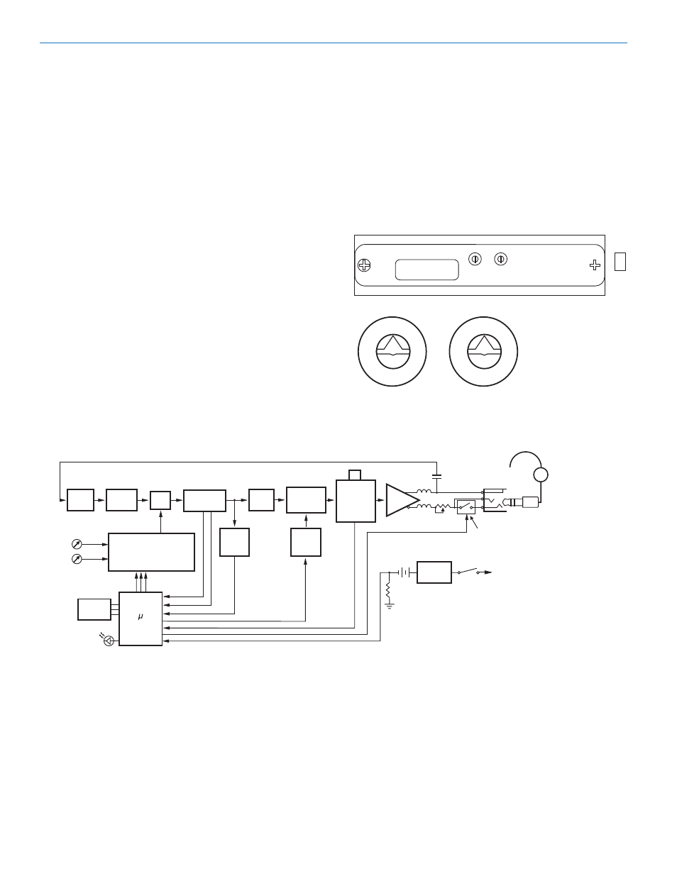
Headphone Jack (fig. 1)
On the front panel is a 3.5mm mini phone jack to
accommodate a standard mono or stereo type 3.5 mm
plug. The unit will drive low or high impedance ear
phones. The jack is also the receiver antenna input with
the earphone cord acting as the antenna. The cord
length is not critical but must be at least 6 inches
minimum.
Mono Plug/Stereo Plug Usage
A Mono plug or a Stereo plug can be used with the
IFBR5a headphone jack directly. When a Mono plug is
inserted, a special circuit senses the “ring” to “sleeve”
short and automatically switches off the ring to prevent
excess battery drain. To reset, switch power OFF then
back ON.
Audio Level
Headphones and ear pieces vary widely in their sensi
tivity and their impedance making it impossible to
design a receiver with a fixed output power level that is
correct for all situations. High impedance phones (600
to 2000) Ohms will have an inherently lower power level
due to their high impedance and likewise low imped
ance phones may be extremely loud. CAUTION!
Always set the Audio Level knob to minimum (counter
clockwise) when plugging phones into the jack, then
adjust the knob for a comfortable audio level.
Frequency Adjust (fig. 2)
These two rotary switches adjus t the center frequency
of the carrier. The 1.6M is a coarse adjustment and the
100K is the fine adjustment. Each transmitter is factory
aligned at the center of its operating range. The default
position of the frequency select switches is in the center
of the transmitter’s range. The receiver and transmitter
switches must be set to the same number/letter combi
nation for proper operation.
To gain access to these switches, slide the access door
sideways with a fingernail.
FREQUENCY
COARSE
FINE
0 1
2
3
4
5
6
8
9
0 1
2
3
4
5
6
8
9
0
1
2
3
4
5
6
7
8
9
A
B
C
D
E
F
0
1
2
3
4
5
6
7
8
9
A
B
C
D
E
F
Figure 2 - Frequency Adjustment
Memory
Controller
Control
Panel
Compandor
Audio
Filter
Audio Out
IF Amp/FM
Detector
5V
Regulator
9V
Battery
On/Off
Amp
Mixer
100n
100n
2p
Disc
RSSI
RF
Filter
RF
Amplifier
Frequency Synthesizer
PB Switch
Pwr On/Off,
Audio Level.
Control
Knob
Pilot
Tone
Detector
Pilot
Tone
Mute
Cord
(Ant.)
Earphone
2.5vdc
2.5vdc
MAX
LEVEL
MONO PLUG (Open)
STEREO PLUG (Closed)
S
T
R
Freq
Switches
LED
Figure 3 - R5a Block Diagram
LECTROSONICS, INC.
6