Front panel description, Rear panel description – Lectrosonics UMC195d User Manual
Page 5
Rack Mount Multi-Channel Systems
FRONT PANEL DESCRIPTION
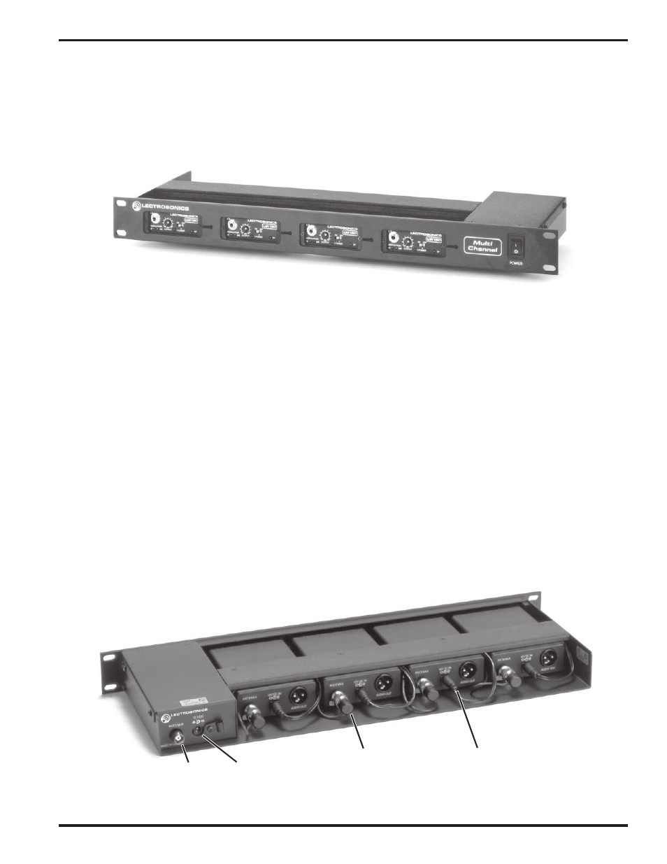
The front panel contains only one control - the Power switch.
Many different receivers can be mounted within the frame. Please refer to the separate receiver manual for a
description of the controls and features of each individual receiver.
Multi Channel System Front View (UMC190 with UR190 receivers shown)
REAR PANEL DESCRIPTION
RF/POWER DISTRIBUTION MODULE
SERIAL/FREQUENCY LABEL
This label indicates the serial number of the DM4 module. It also indicates the RF pass-band of the unit.
IMPORTANT - The receivers installed in the unit must fall between the frequencies indicated on the label. Serious
signal loss results if the receivers are outside the RF pass-band.
ANTENNA
Diversity units will have an “A” and a “B” antenna jack. This is a standard 50 Ohm BNC-F. Antennas connected to
these jack will have their signal filtered, amplified and distributed to each receiver via the BNC output plugs.
12 VDC - DC
Power input jack. Any positive DC supply from 12 to 24 VDC may be used. The jack accepts standard coaxial power
plugs with center pin positive. The polarity is marked on the rear of the unit. DC power applied to this jack will be
distributed to the four coaxial power plugs that power the individual receivers.
RF Output
DC Output
Antenna In
12 VDC In
to Receiver
to Receiver
Multi Channel System Rear View (RDM4 with R175 Receivers shown)
Rio Rancho, NM – USA
5