Introduction, General technical description, Figure 1 - pro 4 channel block diagram 2 – Lectrosonics Pro 4 Channel User Manual
Page 3
GENERAL TECHNICAL DESCRIPTION
The PRO 4 CHANNEL consists of two sub-systems; the frame which contains the receivers, receiver mounting
hardware, and DC power supply, and the CDM4 RF/power distribution module.
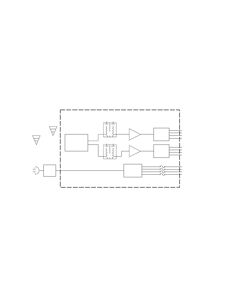
The DM4 RF/power distribution module is the heart of the PRO 4 CHANNEL system. Helical resonators in the front
end of the RF section attenuate out-of-band RF signals preventing intermodulation and front end overload.
Following the resonators is a low noise, low gain RF amplifier designed to evenly compensate for splitter losses in
the stage that follows. A precision splitter/isolator divides the RF signal into four isolated signals preventing
spurious RF coupling between receivers. The splitter/isolator is termination independent which prevents
mismatched or disconnected RF outputs from affecting the other receivers.
Power is supplied to the DM4 module from the DC power supply module mounted on the frame. All power circuits
are protected by internal auto-reset fuses in the DM4. Should the power to one receiver fail, the others will
continue to operate.
RF FILTERING & DISTRIBUTION
POWER SUPPLY & DISTRIBUTION
POLYFUSES
REGULATOR
HELICAL
RESONATORS
SPLITTER
AND/OR
COMBINER
RF
AMP
SPLITTER
&
ISOLATOR
SPLITTER
&
ISOLATOR
RF
AMP
DM4 Diversity Module
POWER
SUPPLY
RF to
Receivers
12V DC Power
to Receivers
Figure 1 - PRO 4 CHANNEL Block Diagram
2