Front panel controls and functions, Power led, Pilot led – Lectrosonics UCR205d User Manual
Page 6: Transmitter mod level meter, Rf level indicators, Power switch (and pilot disable), Pilot tone disable, Audio output level control, Antenna connectors, Antenna phase leds
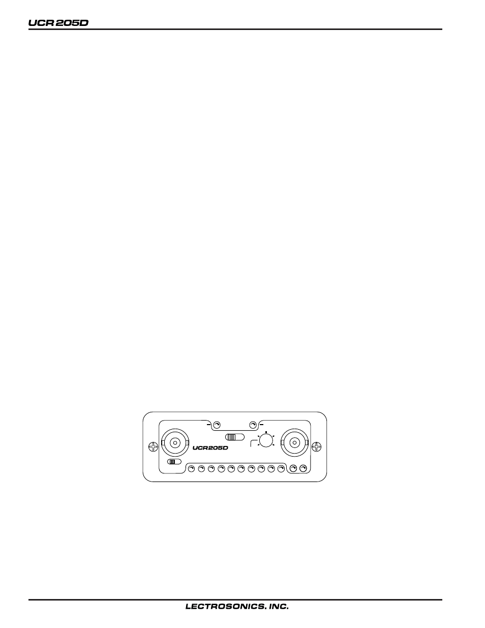
FRONT PANEL CONTROLS AND FUNCTIONS
POWER LED
When lit, this LED indicates that power is applied to the
UCR205D and adequate voltage is present to operate the unit.
PILOT LED
The audio output muting (squelch) function of the UCR205D is
controlled by a 32kHz tone modulation of the RF carrier. The
audio output is muted until this tone is present. This green LED
will remain on as long as the receiver audio is enabled by the
pilot tone.
TRANSMITTER MOD LEVEL METER
When the meter function switch is in the Mod position, the
modulation (audio level) of the incoming signal is indicated by
a fast responding LED strip. The strip is calibrated in 6dB steps
over an expanded scale (54dB) which provides an extremely
accurate visual “picture” of the signal dynamics, even at a
distance away from the receiver. Audio signal peaks easily
exceed the response time of VU meters, however, the LED strip
is fast enough to track even brief transients.
RF LEVEL INDICATORS
With the meter function switch in the RF position, the LED strip
indicates the level of the incoming RF signals. The LED strips
are calibrated to provide accurate indications from 1uV to 1mV.
The LEDs are highly visible from a distance, making antenna
set up more accurate. The LED strip is especially useful in
“troubleshooting” difficult antenna installations.
POWER SWITCH (and PILOT DISABLE)
This slide switch, and its corrosponding LED indicator, switches
the receiver from Off to On with Pilot enabled or ON with Pilot
disabled. The pilot LED will glow green when pilot tone is
present, With the switch in the “ON (Pilot Off)” position, the
LED will glow red. At turn on and off there is a delay built into
the receiver to allow various stages to stabilize before the audio
output is activated. This will prevent an audio “thump” when
powering up the receiver.
PILOT TONE DISABLE
The Power switch on the front panel is the Pilot Tone Disable.
This is a three position switch. The position toward the right (as
seen looking straight at the front panel) is the normal operating
position and allows the pilot tone to enable or disable the
receiver audio output. The other position, toward the left, will
disable the pilot tone action and will cause the receiver audio
output to always be enabled, even in the absence of a transmit
ter signal. This position is only used for troubleshooting and
should never be set during actual use. When the pilot tone is
disabled with this switch, the Mod meter on the front panel is
also disabled.
AUDIO OUTPUT LEVEL CONTROL
The front panel Audio Output Level control will adjust the
audio output within the range set by the Lo/Mid/Hi range
switch (located on the rear panel.) In the Low position the
adjustment range is from –50dBm to –20dBm, the High posi
tion (center) allows an adjustment from –30dBm to 0dBm, and
the Fixed position sets the audio output to a fixed +8dBm with
no front panel control.
ANTENNA CONNECTORS
These are standard 50 Ohm BNC type jacks for the RF input to
the receiver. The left jack is the main antenna (0) and the right
jack is for the diversity antenna (180).
ANTENNA PHASE LEDs
These two LEDs labeled “0” and “180” show the phase differ
ence of the signals being received at the two antennas.
MOD
1mV
10uV
-42
RF
1uV
-36 -30
POWER
ON
(PILOT OFF)
100uV
-12
-18
-24
-6
0dB
ON
OFF
PILOT
0
180
MAIN
DIVERSITY
AUDIO OUT
6