Chapin 7215072 User Manual
Warning, Parts, piezas, pièces, Pre-use check 5. filling
6-8138
Shut-off Handle
Mango de cierre
Poignée du robinet
Hazard: Improper use or failure to follow instructions can result in explosive failure causing serious eye
or other injury.
For safe use of this product you must read and follow all instructions. Do not leave a pressur-
ized sprayer in the hot sun. Heat can cause pressure build-up. Do not store or le
ave solution in tank after use.
Always wear goggles, gloves, long sleeve shirt, long pants and full foot protection when spraying. Never use
any tool to remove pump if there is pressure in sprayer. Never stand with face or body over
top of tank when
pumping or loosening pump to prevent ejecting pump assembly and/or solution from striking and injuring
you. Never pressurize sprayer by any means other than the original pump. Do not attempt to modify or repair
this product except with original manufacturer’s parts. Never spray flammable materials or heat, pressure, or
gas producing chemicals. Always read and follow manufacturer’s instructions before use with this sprayer
as some chemicals may be hazardous when used with this sprayer.
WARNING!
Sk-1113-1
Parts, Piezas, Pièces
6-8130
Hose
Manguera
Tuyau
Repair Parts Kit Gaskets and Seals (not included),
Juego de piezas de reparación, empaquetaduras y juntas (no incluido)
Kit de pièces de réparation, joints et garniture d’étanchéité (non inclus) 6-1925
Printed in U.S.A., Impreso en E.U.A, Imprimé aux U.S.A.
1) Do: Check tightness of hose nut to be sure hose is securely attached to the tank outlet.
2) Do: Inspect hose for deterioration, cracks, softness, or brittleness. If any of these conditions are found, replace hose
before using. Replace with original manufacturer’s parts only.
3) Do: Remove pump (see Filling, Pressurizing and Spraying Instructions), inspect interior and exterior of tank for signs
of deterioration of body and bottom. Any sign of deterioration indicates possible tank weakening and could result in
explosive bursting under pressure. If any of these signs are found, discard tank immediately and replace. Do not attempt
to patch leaks, etc., as this could result in serious injury.
4) Do: Follow Filling, Pressurizing and Spraying Instructions, except use water only.
5) Do: Pump plunger 10-20 strokes and inspect for leaks.
6) Do: Direct shut-off away from you and open to make sure discharge is not clogged.
7) Do: If unit passes this test, release pressure (see Pressure Releasing Instructions), empty tank, and proceed with Filling,
Pressurizing and Spraying Instructions.
4. Pre-Use Check
5. Filling
1) Do: Turn pump handle counterclockwise and remove pump
2) Do: Prepare spray solution following all directions and safety warnings on chemical label.
3) Do: Fill tank to no more than the proper gallon marker. Do NOT: overfill to accommodate pump.
4) Do: Check pump to make sure that no grass or dirt is stuck to barrel. Replace pump in tank and tighten securely.
6. Pressurizing and Spraying
8. Care, Storage and Maintenance
1) Do: Rinse tank thoroughly with water only, empty, refill with water. Follow Filling, Pressurizing and Spraying
Instructions, except pump unit only 8-10 strokes.
2) Do: Open shut-off and allow water to run through discharge assembly.
3) Do: Release pressure (Follow Pressure Release Instructions), remove pump and empty sprayer.
4) Do: Store sprayer tank upside down, with pump removed, in a warm dry location.
5) Do: Periodically oil pump by dropping 10-12 drops of light oil down pump rod through opening in cover.
011207 (A) R0210
6-5364
Measure Cup
Taza para medir
Tasse à mesurer
Adjust spray pattern
by turning nozzle cap.
Do not turn cap more
than 2 turns or cap may
come off allowing spray
material to spray back
on you.
7. To Release Pressure
Do:
With valve facing away from you, lift and hold the cap until air is completely ex-
hausted, OR, turn the valve slowly counterclockwise until you hear air escaping and wait
air is completely exhausted.
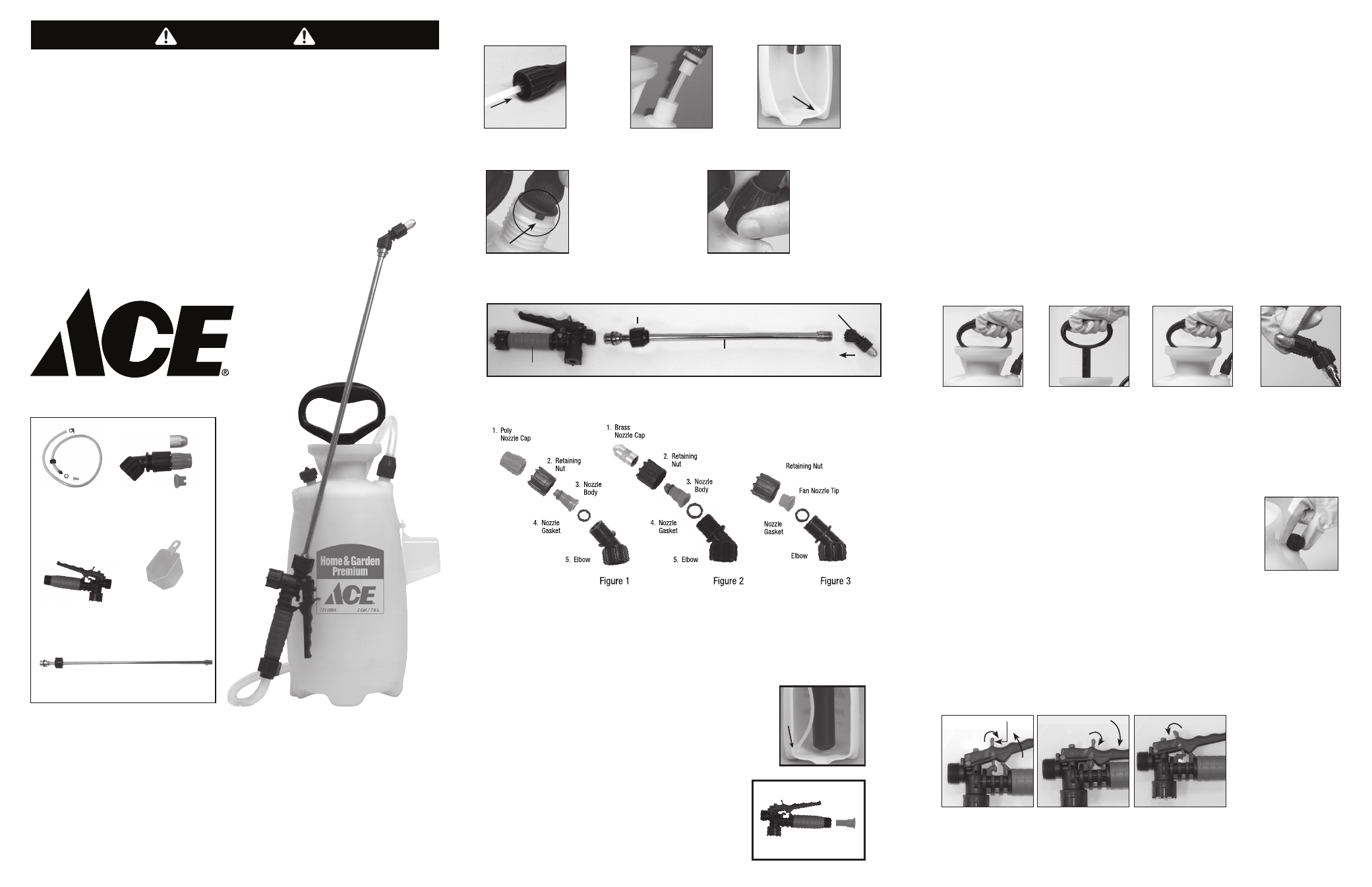
1. Hose to Tank
Make sure white outlet tube
is attached to hose.
Insert tube into tank.
Proper placement of
white outlet tube.
Line up tabs on safety
lock connector with
notches on the outlet
flange of the tank. Insert
tabs into notches to form
a secure seal.
Slip hose nut down to
tank, turn clockwise
and tighten as tight as
possible by hand.
Note:
Your particular sprayer may not include all parts pictured above.
Nota:
Es posible que este pulverizador en particular no incluya todas las partes que se ilustran arriba.
Remarque :
Votre pulvérisateur particulier pourrait ne pas inclure toutes les pièces illustrées plus haut.
Do:
Turn handle clock-
wise to tighten. Push
handle down, turn 1/4
turn counterclockwise
to release.
Do:
Pump until you
feel resistance.
Do:
Push handle,
down, turn 1/4 turn
clockwise to lock. Begin
spraying. Re-pump
sprayer as required to
maintain spray force.
1A
1B
1C
1D
1E
7A
9. Fatigue-Free Spraying
3. Filter
The filter helps prevent clogging while spraying. It is located on the end of the outlet
tube inside your sprayer tank.To clean filter, remove the discharge assembly from the
tank (Fig. 3A). Make sure the filter is positioned at the bottom of the tank as pictured.
Filter
3A
6B
6A
6C
6D
WARNING:
Handling the brass parts of this product will expose you to lead, a chemical
known to the State of California to cause birth defects and other reproductive harm.
Wash hands after handling.
6-8133
Extension wand,
Vara de extensión, Rallonge
2. Assembly of Shut-off, Extension Wand and Nozzle
1) Screw nozzle assembly onto threaded end of the extension wand securely.
2) Insert unthreaded end of extension into shut-off assembly as shown and tighten retaining nut securely.
Nozzle Assembly
Figure 1-2
Unscrew the nozzle cap (1) from the nozzle body (3) with retaining nut (2) fastened tightly to the elbow (5). Unscrew the
retaining nut (2). Push the nozzle body (3) with the nozzle gasket (4) out of the retaining nut (2). To reinstall the nozzle,
reverse the above instructions.
Figure 3
Unscrew the retaining nut from the elbow and push the fan nozzle tip and gasket out of the retaining nut. To reinstall the
nozzle, reverse the above instructions.
Shut-off Assembly
Retaining Nut
Extension Wand
Nozzle Assembly
2a
For safety lock-off feature (no-spraying), pull up on handle and move red locking mechanism into lock-off position as shown
in fig. 9a. To disengage, push down on handle and return red locking mechanismto neutral position as in fig. 9c. For lock-on
feature (continuous spraying), push down on handle and move red locking mechanism into lock-on position as shown in fig. 9b.
To disengage, push down on handle and return red locking mechanism to neutral position as shown in fig. 9c.
9a
9b
9c
Locking Mechanism
Handle
Up
Handle
Down
LOCK-OFF POSITION
LOCK-ON POSITION
NEUTRAL POSITION
6-8131
Nozzle
Tobera
Buse
The filter is a removable filter incorporated into the inlet side of the shut-off
valve. To clean filter make sure pressure is released before detaching the hose
from the shut-off. It is best to have no or minimal fluid in the pressure
chamber before removing and reinstalling the shut-off filter as fluid can leak
from the hose (Fig. 3B).
3B