7330 series, Installation instructions – KING 7330 Series User Manual
Page 4
(714) 891-0008 • www.kinginstrumentco.com
When it comes to flow...we’re instrumental.
4
7330 Series
Installation Instructions
Installation Instructions
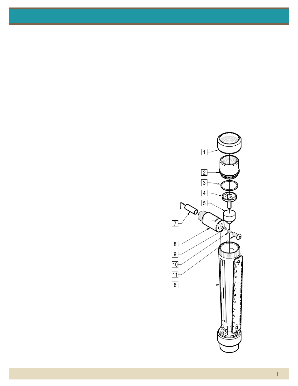
7330 series asseMbly with latching reed switch
parts list:
1. End Fitting Union Nut
2. End Fitting
3. End Fitting O-Ring
4. Float Stop/ Extension Assembly
5. Float
6. Polysulfone Meter Tube Assembly
7. Alarm Switch
8. Alarm Switch Housing
9. Alarm Set Screw O-Ring
10. Alarm Set Screw
11. Alarm Switch Housing Screw
7330 series latching reed switch
All 7330 Series flowmeters may be fitted with one or two latching
reed switches.
The switch assembly is mounted on the meter tube. The switch can
be positioned to trip at any point on the scale.
The switch is a reed type and uses a biasing magnet to give it the
latching feature. The float contains hermetically sealed magnet(s),
so when the float comes in proximity to the switch it closes and
remains closed (latched) when the float moves below the switch it
resets itself. Contact King Instrument Company for multiple switch
options.
latching reed switch electrical speciFications
type:
spdt / latching
MAXIMUM CONTACT VOLTAGE:
100V DC
MAXIMUM CONTACT CURRENT:
0.20 A DC
MAXIMUM CONTACT POWER:
4 Watts DC
BREAKDOWN VOLTAGE:
200V DC
STANDARD PULL-IN RANGE:
15-40 Ampere turns
INITIAL CONTACT RESISTANCE:
0.150 Ohm
connections - intrinsically saFe wiring
SWITCH ISOLATER 3 CONDUCTOR, 22Awg, 2’ Long
1) White - N.O. switch output 1
2) Red - common
3) Black - N.C. switch output 2
switch isolator option:
Latching reed switches can be used as stand alone devices, or may
be connected to a switch isolator for intrinsically safe applications.
The purpose of the switch isolator is to supply electrical signals
between safe and hazardous areas in either direction while limit-
ing the amount of energy that can be transferred even under fault
conditions. Switch isolators are available with 220 VAC, 110 VAC or
24 VDC supply voltage requirements, contain single pole double
throw (SPDT) relays, and are DIN rail mountable. See switch isolator
specifications for electrical connections and further details.
12700 Pala Drive, Garden Grove, CA 92841
www.kinginstrumentco.com / (714) 891-0008
Meters are warranted against defects in materials and workmanship
to the original user for a period of thirteen (13) months from the date
of factory shipment, provided the meter is installed, operated and
maintained in accordance with King Instrument Company's
instructions and recommendations.
This warranty does not apply if failure is caused or contributed to by
any of the following: improper handling, improper storage, abuse,
unsuitable application of the product, lack of reasonable and
necessary maintenance, use exceeding suggested pressure and
temperature maximums, improper packaging for return, or repairs
made or attempted to be made by anyone other than King Instrument
Company, Inc.
KING INSTRUMENT COMPANY, INC. MAKES NO
WARRANTY AS TO THE FITNESS OF ITS PRODUCTS
FOR SPECIFIC APPLICATIONS.
This warranty is valid for the original end-user only and does not
apply to products that have been damaged or modified. This
warranty is non-transferrable and is limited to replacement or repair.
The liability of King Instrument Company arising out of its supply of
the products, or their use, shall not in any case exceed the cost of
correcting defects in the products as set forth above.
THIS WARRANTY IS A LIMITED WARRANTY AND
SHALL BE IN LIEU OF ANY OTHER WARRANTIES,
EXPRESSED OR IMPLIED, INCLUDING BUT NOT
LIMITED TO ANY IMPLIED WARRANTY OR
MERCHANTABILITY OR FITNESS FOR A PARTICULAR
PURPOSE. THERE ARE NO OTHER WARRANTIES
WHICH EXIST BEYOND THE DESCRIPTION OR FACE
HEREOF.
IN NO EVENT SHALL KING INSTRUMENT COMPANY BE
LIABLE FOR LOSS OF PROFITS, INDIRECT,
CONSEQUENTIAL OR INCIDENTAL DAMAGES.
Products should be returned, prepaid, to King Instrument Company,
Inc. with proof of purchase. Call factory for Return Merchandise
Authorization (RMA) number and return instructions.
2013A
All 7330 Series flowmeters may be fitted with one or two latching reed switches.
The switch is a reed type and uses a biasing magnet to give it the latching
feature. The float contains hermetically sealed magnet(s), so when the float
comes in proximity to the switch it closes and remains closed (latched) when
the float moves below the switch it resets itself. Contact King Instrument
Company for multiple switch options.
LATCHING REED SWITCH ELECTRICAL
SPECIFICATIONS
TYPE:
MAXIMUM CONTACT VOLTAGE:
MAXIMUM CONTACT CURRENT:
MAXIMUM CONTACT POWER:
SPDT / Latching
100V DC
0.20 A DC
4 Watts DC
BREAKDOWN VOLTAGE:
200V DC
STANDARD PULL-IN RANGE:
15-40 Ampere turns
INITIAL CONTACT RESISTANCE:
0.150 Ohm
SWITCH ISOLATER 3 CONDUCTOR, 22Awg, 2' Long
END FITTING
END FITTING O-RING
FLOAT
EXTENSION ASSEMBLY
ALARM SWITCH HOUSING
FLOAT STOP/
ALARM SWITCH
ALARM SET SCREW
ALARM SWITCH HOUSING
UNION NUT
END FITTING
POLYSULFONE
The switch assembly is mounted on the meter tube. The switch can be
positioned to trip at any point on the scale.
CONNECTIONS - INTRINSICALLY SAFE WIRING
1) White - N.O. switch output 1
2) Red - common
3) Black - N.C. switch output 2
SWITCH ISOLATOR OPTION:
Latching reed switches can be used as stand alone devices, or may be
connected to a switch isolator for intrinsically safe applications. The purpose of
the switch isolator is to supply electrical signals between safe and hazardous
areas in either direction while limiting the amount of energy that can be
transferred even under fault conditions. Switch isolators are available with
220VAC, 110VAC or 24VDC supply voltage requirements, contain single pole
double throw (SPDT) relays, and are DIN rail mountable. See switch isolator
specifications for electrical connections and further details.
METER TUBE ASSEMBLY
ALARM SET SCREW
O-RING
SCREW