7910 series, Installation instructions, Latching reed switch – KING 7910 Series User Manual
Page 5: Latching reed switch-electrical specifications, Connections - intrinsically safe wiring, Switch isolator option, Float types and orientations, 7480 series assembly with alarm parts list
(714) 891-0008 • www.kinginstrumentco.com
When it comes to flow...we’re instrumental.
5
7910 Series
Installation Instructions
latching reed switch
All 7910 Series flowmeters may be fitted with one or two latching reed
switches.
The switch assembly is mounted on the guide rod. The switch can be
positioned to trip at any point on the scale.
The switch is a reed type and uses a biasing magnet to give it the
latching feature. The float contains hermetically sealed magnet(s), so
when the float comes in proximity to the switch it closes and remains
closed (latched) when the float moves below the switch it resets itself.
Contact King Instrument Company for multiple switch options.
latching reed switch-electrical
speciFications
TYPE:
SPDT
/
Latching
MAXIMUM CONTACT VOLTAGE:
100V DC
MAXIMUM CONTACT CURRENT:
0.20 A DC
MAXIMUM CONTACT POWER:
4 Watts DC
BREAKDOWN VOLTAGE:
200V DC
STANDARD PULL-IN RANGE:
15-40 Ampere turns
INITIAL CONTACT RESISTANCE:
0.150 Ohm
connections - intrinsically saFe wiring
SWITCH ISOLATER 3 CONDUCTOR, 22Awg, 2’ Long
1) White - N.O. switch output 1
2) Red - common
3) Black - N.C. switch output 2
switch isolator option:
Latching reed switches can be used as stand alone devices, or may be
connected to a switch isolator for intrinsically safe applications. The
purpose of the switch isolator is to supply electrical signals between
safe and hazardous areas in either direction while limiting the amount
of energy that can be transferred even under fault conditions. Switch
isolators are available with 220VAC, 110VAC or 24VDC supply voltage
requirements, contain single pole double throw (SPDT) relays, and are
DIN rail mountable. See switch isolator specifications for electrical con-
nections and further details.
Float types and orientations
GV FLOAT
GS FLOAT
LP FLOAT
SL FLOAT
Pressure and temperature ratings are based on a study of the engineering data for
particular materials used in construction and on the design of individual models.
This information is supplemented by destructive test results. Meters with stainless
enclosures must never be operated without shields securely in place. Meters
exposed to difficult environments such as those created by certain chemicals,
excessive vibration or other stress inducing factors could fail at or below the
suggested maximums. Never operate meters above pressure and temperature
maximums. It is strongly recommended that all meter installations utilize an
appropriate pressure relief valve and/or rupture disc. The pressure settings and
locations of these devices should be such that meters cannot be over pressurized.
Meter failure could result in damage to equipment and serious personal injury.
Always use suitable safety gear, including OSHA approved eye protection when
working around meters in service. We are happy to pass along chemical
compatibility information that has been published by the manufacturer's of raw
materials used in our products; however, this information should not be construed
as a recommendation made by King Instrument Company, Inc. for a specific
application.
Carefully remove the flowmeter from piping system. Remove the 4 screws on each
side holding the side plates on. Remove the side plates. Carefully remove the glass
meter tube from the end fittings. Be sure to not let the internals fall out. Use caution
when removing the glass meter tube. Do not allow float to fall out. Float damage
may result in inaccuracy. All necessary instrument components are now fully
accessible for cleaning with a bottle brush and appropriate mild soap solution*.
Before the meter is reassembled, inspect all parts for damage. O-rings should be
replaced during meter maintenance and cleaning.
To reassemble, install the glass meter tube back onto the end fittings. Reinstall the
side plates. Tighten the 4 screws on each side. Reinstall the instrument into the
plumbing system after removing the old teflon tape (with a wire brush) and
replacing with fresh teflon tape.
*Do not use cleaning agents that will damage float, tube or o-rings.
Meters should be cleaned with a mild soap solution. This will be an effective
cleaner of rust stains. Caution must be used so that materials of construction are
not damaged by cleaning solutions. Hard water deposits can be removed with 5%
acetic acid solution (vinegar).
7460 meters that require repair should be sent to the factory. Please call for a
Return Merchandise Authorization (RMA) number and return instructions.
-O-rings should be replaced if meter is disassembled after it has been in service.
-Serious property damage and great personal injury could occur as the result of a
meter misused or used in an unsuitable application.
CAUTION:
CLEANING:
REPAIR:
WARNING:
FLOAT TYPES AND
ORIENTATIONS:
LP FLOAT
Maximum flow meter
capacity with limited
viscosity immunity
GV FLOAT (Rib Guided)
Highest immunity to
viscous fluids with
medium capacity.
SL FLOAT
Maximum flow meter
capacity with limited
viscosity immunity
GS FLOAT (Rib Guided)
Maximum flow meter
capacity with limited
viscosity immunity
SP FLOAT
Maximum flow meter
capacity with limited
viscosity immunity
GV FLOAT (Pole Guided)
Highest immunity to
viscous fluids with
medium capacity.
GS FLOAT (Pole Guided)
Maximum flow meter
capacity with limited
viscosity immunity
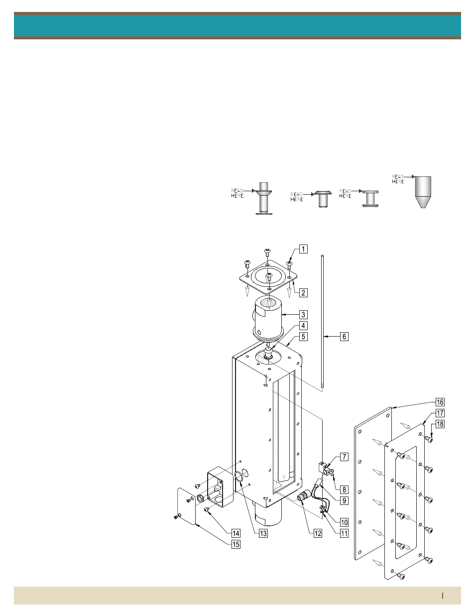
7480 series asseMbly
with alarM
parts list:
1. End Fitting Retainer Screw
2. End Fitting Retainer
3. End Fitting Assembly
4. Magnetic Float
5. Case Assembly
6. Alarm Guide Rod
7. Alarm Switch Housing
8. Alarm Switch Housing Set Screw
9. Alarm Switch
10. Alarm Guide Rod Nut
11. Alarm Guide Rod Lock Washer
12. Electrical Strain Connector
13. Junction Box O-Ring
14. Junction Box With Cover
15. Junction Box Mounting Screw
16. Shield (Clear)
17. Shield Cover
18. Shield Cover Screw
1) Inspect meter for damage that may have occurred during shipping. Report any
damage to the container to the freight carrier immediately.
This is important information. Read it carefully before
beginning work.
2) Make sure your pressure, temperature, fluid and other requirements are
compatible with the meter including o-rings.
3) Select a suitable location for installation to prevent excess stress on the meter
which may result from:
a) Misaligned pipe.
b) The weight of related plumbing.
c) "Water Hammer" which is most likely to occur when flow is suddenly stopped
as with quick closing solenoid operated valves. (If necessary, a surge chamber
should be installed. This will also be useful in pressure start-up situations.)
d) Thermal expansion of liquid in a stagnated or valve isolated system.
e) Instantaneous pressurization which will stress the meter and could result in
tube failure.
NOTE: In closed thermal transfer or cooling systems, install the meter in the cool
side of the line to minimize meter expansion and contraction and possible fluid
leaks at the threaded connections.
4) Handle the meter carefully during installation.
a) Use an appropriate amount of teflon tape on external pipe threads before
making connections. Do not use paste or stick type thread sealing products.
5) Install the meter vertically with the inlet port at the bottom.
Maximum Non-Shock
Pressure and Temperature O-Ring Temperature
b) Over tightening of plastic connections may result in fitting damage.
6) Connections: Fittings are fully rotatable by loosening the fitting retainer screws
during installation. Make sure fitting retainer screws are tightening after adjustment
of fitting.
7) Meters with stainless steel fittings will support several feet of pipe as long as
significant vibration or stress resulting from misaligned pipe are not factors.
8) Meters with plastic fittings must be installed so that fittings are not made to
support any part of the associated plumbing. In addition, meter frame should be
fastened to bulkhead, panel or column.
9) Meters used in gas service should have suitable valves plumbed in at the inlet
and outlet of the meter. These valves should be no more than 1-1/2 pipe diameters
from the meter ports. The valve at the outlet should be used to create back
pressure as required to prevent float bounce. It should be set initially and then left
alone. The inlet valve should be used for throttling purposes. Depending on the
installation, valves may not be essential, but they are most useful in many
installations. Remember: To get a correct reading of flow in gas service, it is
necessary to know the pressure right at the outlet of the meter (before the valve).
Viton and Kalrez are registered trademarks of DuPont Dow Elastomers.
Ambient temperature
33° F - 125° F
EPR
225 °F
Buna-N
Viton
Kalrez
275 °F
350 °F
400 °F
300 psig
(31W-46W)
200°F
Maximum
Temperature
O-Ring
Material
250 psig
(51W-613W)
150 psig
(84W-99W)
Pressure
(PVC)
Pressure
(316LSS)
150 psig
(31W-613W)
125 psig
(84W-99W)
Temperature
(PVC)
Temperature
(316LSS)
110°F
END FITTING RETAINER
END FITTING RETAINER
END FITTING ASSEMBLY
MAGNETIC FLOAT
CASE ASSEMBLY
ALARM GUIDE ROD
ALARM SWITCH HOUSING
ALARM SWITCH HOUSING
ALARM SWITCH
ALARM GUIDE ROD
ALARM GUIDE ROD
ELECTRICAL
JUNCTION BOX O-RING
JUNCTION BOX
JUNCTION BOX MOUNTING
SHIELD (CLEAR)
SHIELD COVER
SHIELD COVER SCREW
2X
8X
4X
2X
SCREW
SET SCREW
NUT
LOCK WASHER
STRAIN CONNECTOR
WITH COVER
SCREW