7720 series, Installation instructions – KING 7720 Series User Manual
Page 2
(714) 891-0008 • www.kinginstrumentco.com
When it comes to flow...we’re instrumental.
2
7720 Series
Installation Instructions
caution
• O-rings should be replaced if meter is disassembled
after it has been in service.
• Do not loosen nuts that fasten indicator housing
to metering tube. If the relationship of meter tube
and indicator housing are changed, meter must be
calibrated.
• Serious property damage and great personal injury
could occur as the result of a meter misused or used in
an unsuitable application.
repair
7720 meters that require repair should be sent to the
factory. Please call for aReturn Merchandise Authoriza-
tion (RMA) number and return instructions.
warning:
Pressure and temperature ratings are based on a study
of the engineering data for particular materials used in
construction and on the design of individual models.
This information is supplemented by destructive test
results. Meters with stainless enclosures must never
be operated without shields securely in place. Meters
exposed to difficult environments such as those created
by certain chemicals, excessive vibration or other stress
inducing factors could fail at or below the suggested
maximums. Never operate meters above pressure and
temperature maximums. It is strongly recommended
that all meter installations utilize an appropriate pres-
sure relief valve and/or rupture disc. The pressure set-
tings and locations of these devices should be such that
meters cannot be over pressurized. Meter failure could
result in damage to equipment and serious personal
injury. Always use suitable safety gear, including OSHA
approved eye protection when working around meters
in service. We are happy to pass along chemical com-
patibility information that has been published by the
manufacturer’s of raw materials used in our products;
however, this information should not be construed as a
recommendation made by King Instrument Company,
Inc. for a specific application.
max non-Shock Pressure and temperature
fitting
temp
Size
4 and 6
Size
8 thru 12
fNPT
130°F Max
150 psig
125 psig
150# Flange 130°F Max
150 psig
150 psig
300# Flange 130°F Max
150 psig
150 psig
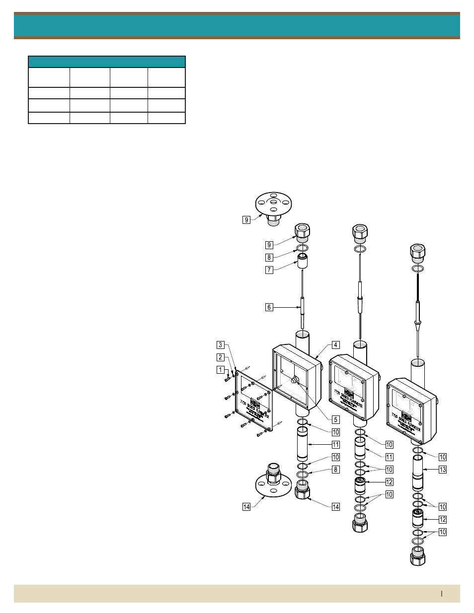
7720 series asseMbly
parts list:
1. Shield Screw
2. Shield Screw O-Ring
3. Shield With Gasket
4. Indicator Housing/Meter
Tube Assembly
5. Pointer Needle Set Screw
6. Float
7. Outlet Float Stop Housing
Assembly
8. End Fitting O-Ring
9. Outlet End Fitting
10. Orifice Housing O-Ring*
11. Orifice Housing/ Orifice
Assembly*
12. Inlet Float Stop Housing
Assembly*
13. Taper Sleeve*
14. Inlet End Fitting
*CONFIGURATIONS VARY BY FLOW
RATE AND METER SIZE.
Pressure and temperature ratings are based on a study of the engineering data
for particular materials used in construction and on the design of individual
models. This information is supplemented by destructive test results. Meters with
stainless enclosures must never be operated without shields securely in place.
Meters exposed to difficult environments such as those created by certain
chemicals, excessive vibration or other stress inducing factors could fail at or
below the suggested maximums. Never operate meters above pressure and
temperature maximums. It is strongly recommended that all meter installations
utilize an appropriate pressure relief valve and/or rupture disc. The pressure
settings and locations of these devices should be such that meters cannot be
over pressurized. Meter failure could result in damage to equipment and serious
personal injury. Always use suitable safety gear, including OSHA approved eye
protection when working around meters in service. We are happy to pass along
chemical compatibility information that has been published by the manufacturer's
of raw materials used in our products; however, this information should not be
construed as a recommendation made by King Instrument Company, Inc. for a
specific application.
Carefully remove the flowmeter from piping system. Remove the threaded outlet
end fitting and withdraw the float from the top. All necessary instrument
components are now fully accessible for cleaning with a bottle brush and
appropriate mild soap solution*. Before the meter is reassembled, inspect all
parts for damage. O-rings should be replaced during meter maintenance and
cleaning.
To reassemble, carefully guide the magnetic float back into the tube. Reinstall
and tighten outlet end fitting. Reinstall the instrument into the plumbing system
after removing the old teflon tape (with a wire brush) and replacing with fresh
teflon tape.
*Do not use cleaning agents that will damage float, tube or o-rings.
Meters should be cleaned with a mild soap solution. This will be an effective
cleaner of rust stains. Caution must be used so that materials of construction are
not damaged by cleaning solutions. Hard water deposits can be removed with 5%
acetic acid solution (vinegar).
7720 meters that require repair should be sent to the factory. Please call for a
Return Merchandise Authorization (RMA) number and return instructions.
-O-rings should be replaced if meter is disassembled after it has been in service.
-Serious property damage and great personal injury could occur as the result of a
meter misused or used in an unsuitable application.
1) Inspect meter for damage that may have occurred during shipping.
Report any damage to the container to the freight carrier immediately.
This is important information. Read it carefully
before beginning work.
2) Make sure your pressure, temperature, fluid and other
requirements are compatible with the meter and components
(including o-rings).
3) Select a suitable location for installation to prevent excess stress
on the meter which may result from:
a) Misaligned pipe.
b) The weight of related plumbing.
c) "Water Hammer" which is most likely to occur when flow is
suddenly stopped as with quick closing solenoid operated valves.
(If necessary, a surge chamber should be installed. This will also be
useful in pressure start-up situations.)
d) Thermal expansion of liquid in a stagnated or valve isolated
system.
e) Instantaneous pressurization which will stress the meter and
could result in tube failure.
NOTE: In closed thermal transfer or cooling systems, install the meter
in the cool side of the line to minimize meter expansion and
contraction and possible fluid leaks at the threaded connections.
4) Handle the meter carefully during installation.
a) Use an appropriate amount of teflon tape on external pipe
threads before making connections. Do not use paste or stick type
thread sealing products.
5) Install the meter vertically with the inlet port at the bottom.
Maximum Non-Shock
Pressure and
Temperature
O-Ring Temperature
Meters are not specifically recommended for service other than
water or air. The user must determine meter suitability for use
with other fluids.
ADDITIONALLY:
-7720 Series meters are designed for vertical installation only. (Inlet at
bottom, Outlet at top)
-Do not remove or adjust the screws on the side of the indicator
housing. These screws were positioned during factory calibration and
represent the zero adjustment. If the pointer is set on zero, proceed
with installation. If the pointer is not set at zero, follow these steps:
Caution: Zero is factory set when meter is
calibrated. DO NOT loosen screws that fasten
indicator housing to meter body. If indicator
housing is moved, the meter will need to be
calibrated.
1) Remove front cover with gasket from indicator housing.
2) Loosen set screw at the base of the pointer hub.
3) Reposition pointer to zero line.
4) Tighten set screw with a
1
16
" allen wrench by holding the pointer
hub and gently tightening the set screws.
5) Replace front cover with gasket on indicator housing.
-Do not loosen nuts that fasten indicator housing to metering tube. If the
relationship of meter tube and indicator housing are changed, meter must be
calibrated.
6) Meters with plastic fittings must be installed so that fittings are not
made to support any part of the associated plumbing. In addition,
meter frame should be fastened to bulkhead, panel or column.
SHIELD SCREW
SHIELD SCREW O-RING
SHIELD WITH GASKET
INDICATOR HOUSING/
POINTER NEEDLE SET SCREW
FLOAT
END FITTING O-RING
OUTLET END FITTING
ORIFICE HOUSING O-RING
ORIFICE HOUSING/
OUTLET FLOAT STOP
8X
8X
FLANGE
FNPT
METER TUBE ASSEMBLY
ORIFICE ASSEMBLY
HOUSING ASSEMBLY
TAPER SLEEVE
INLET END FITTING
INLET FLOAT STOP
HOUSING ASSEMBLY
FLANGE
1
1
1
1
CONFIGURATIONS VARY BY FLOW RATE AND METER SIZE.
1
EPR
225 °F
Buna-N
Viton
Kalrez
275 °F
350 °F
400 °F
O-Ring
Material
Maximum
Temperature
The maximum ambient
temperature for the indicator
housing is 158°F.
Viton and Kalrez are registered trademarks of DuPont Dow
Elastomers.
1
FNPT
Size
8 thru 12
Size
4 and 6
Temp.
125
psig
150
psig
130°F
Max.
150
psig
150
psig
130°F
Max.
FNPT
150#
Flange
150
psig
150
psig
130°F
Max.
300#
Flange