Connections, Wiring diagram with iva-w200, Specifi cations – Alpine PMD-DOK1 User Manual
Page 2: Installation, Additional on-screen buttons, Features, Confi rming proper installation
Connections
(2A)
(2A)
1
2
3
4
5
6
7
8
9
10
Ground (Black)
ACC (Ignition) (Red)
Mute (Pink/Skyblue)
Open
Open
Open
Battery (Yellow)
Dimmer In (Illumination) (White/Blue)
Speed Sensor (Green/White)
Parking Brake (Yellow/Blue)
Battery Lead
(Yellow)
Dimmer In (Illumination) (+)
(White/Blue)
Speed Sensor (Green/White)
Parking Brake (Yellow/Blue)
Ground (Black)
ACC (Ignition) (Red)
Mute (Pink/Skyblue)
To the Illumination
signal line (+)
To the parking brake
signal line (-)
To AUX
input of
IVA-W200
Power Connector Pin
Configuration
Connect to a metal part
of chassis body with
screw
To the Acc power lead (+)
To Constant 12 V (+)
To Vehicle speed sensor
line input
Use this to connect a
device having the IN-INT
function (-) output for
Audio Mute
GPS Antenna (Included)
Antenna
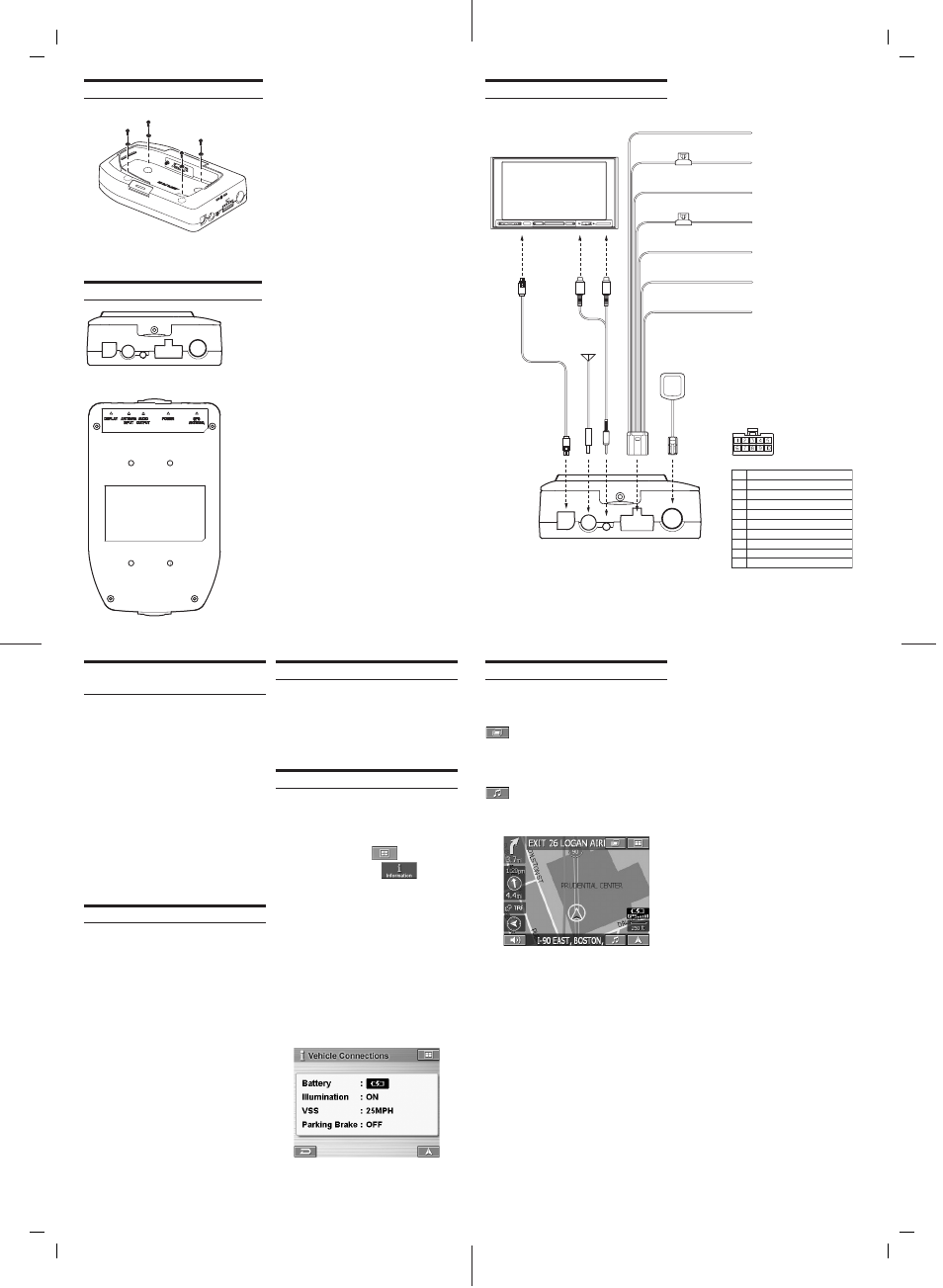
Wiring Diagram With IVA-W200
1
2 3
4
5
1. DISPLAY
Connects to the display connector of Alpine A/V Head Unit.
2.
ANTENNA INPUT (OPTIONAL)
FM antenna input (RDS-TMC traffi c tuner reception).
Optional fi lm antenna (KAX-350FM) available. See your
dealer for details.
3. AUDIO
OUTPUT
Connects to aux input of Alpine A/V Head Unit (using the
provided adapter).
4. Power
Connects 10 pin power input.
5. GPS
Antenna
External GPS antenna (included) Input
Operating Blackbird from the A/V Head
Unit (using IVA-W200 as an example)
1.
Press and hold the power button for 2
seconds to power on Blackbird.
2.
Place Blackbird into the Docking station.
3.
Power on the A/V Head Unit and select
Navigation as Source.
To Listen to Music from Blackbird
4.
Press
SOURCE
and select
AUX
as input.
5.
Press
V.SEL
and select Navigation as video
source.
• Using V. SEL, you can still use function of the A/V Head
Unit while Blackbird is on the screen.
• Blackbird’s music feature is also available from the Navi
menu. See Blackbird Owner’s Manual for more details.
Specifi cations
•
External dimensions
....................................
..................118 (W) x 118 (H) x 40 (D) mm
•
Weight ................................. 0.8 Lb ( 360 g)
•
Included in the box:
PMD-DOK1 Docking Station ..................1
Transparent
Dock
Cover
.........................1
10 pin Power cable (5 m/ 16.4 ft) ............1
13 pin RGB Video cable (5 m/ 16.4 ft) ....1
External GPS antenna (5 m/ 16.4 ft) .......1
Mini jack to RCA (female) cable
(31 cm/ 1 ft) ............................................1
Mounting
screws
....................................4
Cover lock screws ..................................2
Installation/Owner’s
Manual
....................1
Registration
card
....................................1
•
Product specifi cations and appearance are
subject to change without notice for the
purpose of improvement.
Installation
•
Select a location where the PMD-DOK1
Docking Station will be level once installed.
•
Do not install the Docking Station in a position
where the Blackbird main unit will be inserted
upside down.
•
To protect against vehicle noise, leave a
space of 10 to 20 cm between the vehicle
wiring and wiring for the Docking Station
when installing.
•
The Docking Station should be mounted in
a convenient location using the mounting
screws provided.
Additional On-Screen Buttons
When Blackbird is docked, two additional
on-screen buttons allow you to conveniently
access system features.
Touching this button will give you
access to the A/V Head Unit’s display
control.
Note; If left idle for more than 5 seconds, the system will
automatically return to the Blackbird navigation screen.
Touching this button will display
Blackbird’s music screen. Refer to the
Blackbird Owner’s Manual for help
using the music functions.
Features
•
Navigation map display output to A/V Head
Unit
•
Full Touch Control with compatible A/V Head
Unit
•
Vehicle speed sensor input
•
Voice guidance output
•
Stereo MP3/WMA audio output
Confi rming Proper Installation
The vehicle connections screen allows you to
ensure proper installation of the PMD-DOK1.
1.
Touch
NAVI
. The A/V Head Unit will display
the Blackbird screen.
2.
Touch
MAIN MENU
.
3.
Touch
INFORMATION
.
4.
Select
VEHICLE CONNECTIONS
. The
connection status will appear on the screen.
Illumination - Toggle the parking lamp switch on
and off to confi rm this connection. This will allow
the navigation display to change between night
and day mode.
VSS - When connected to the vehicle speed
sensor wire, this number will change to refl ect
current speed.
Parking Brake - Toggle the parking brake on
and off to confi rm this connection. This will allow
access to the Edit and Setup menu while the
vehicle is parked.
PMD-DOK1_r4.indd 2
PMD-DOK1_r4.indd 2
6/14/06 7:06:21 PM
6/14/06 7:06:21 PM