Cashco 5200 User Manual
Page 3
3
IOM-5200
SECTION V
V. INSTALLATION:
The Model 5200 POVV is a precision device that
must be handled carefully to ensure seat tightness.
WARNING
The vent must be installed in a vertical position. The
tank nozzle on which the vent is mounted should have
the same nominal diameter as the venting device. It
is recommended that the tank nozzle ƀ ange face be
within 1 degree of horizontal for best performance of
the venting device.
WARNING
Minimum clearance between tank roof and vacuum
inlet port must be at least equal to the vents’ nomi-
nal ƀ ange bore. Tank nozzle bore must be greater
than or equal to vent inlet ƀ ange bore. Inlet piping
loads must be supported by appropriate structural
supports, NOT by the vent body.
1. At installation, the POVV should be carefully
lifted into position using the lifting lugs on the
body. Use the case assembly (32,33) to help
align the body directly over the tank nozzle.
DO NOT use the pilot valve or pickup line to
pull the POVV into position.
2. Aluminum body vents should be mated to
ƀ at-faced 125# ASME ƀ anges. Mating ƀ anges
should be ƀ at within 0.020” and clean; free
of scratches, corrosion and tool marks. A full
faced gasket is recommended.
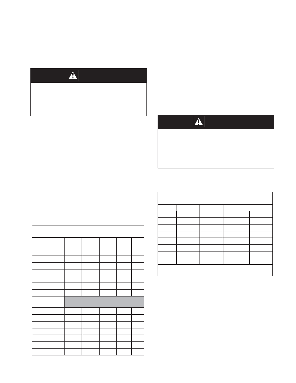
3. Install the ƀ ange gasket on the nozzel face.
Use either a full faced or ring gasket for
raised face ƀ anges. Ensure that the gasket
material is suitable for the service. See Table
1 for gasket dimensions.
Table 1
Body Flange Gasket Dimensions
CS, SST
150# ASME RF
O.D.
I.D.
B.C.
Hole
Qty
2’
4.12
2.38
--
--
--
3”
5.38
3.50
--
--
--
4”
6.88
4.50
--
--
--
6”
8.75
6.62
--
--
--
8”
11.00
8.62
--
--
--
10”
13.38
10.80
--
--
--
12”
16.12
12.80
--
--
--
Alum w/ 125#
ASME FF
2”
6.00
2.00
4.75
.75
4
3”
7.50
3.00
6.00
.75
4
4”
9.00
4.00
7.50
.75
8
6”
11.00
6.00
9.50
.88
8
8”
13.50
8.00
11.75
.88
8
10”
16.00
10.0
14.25
1.00
12
12”
19.00
12.00
17.00
1.00
12
4. Center the gasket within the bolt circle of the
tank
nozzle
ƀ
ange.
5. Lubricate all studs and nuts with an appropri-
ate thread lubricant. If stainless steel studs
and nuts are required, use an anti-seize lubri-
cant such as moly-disulſ de.
6. Remove
ƀ ange protective covers and carefuly
set the POVV down on the gasket and face of
the
nozzle
ƀ
ange.
7. Install lockwashers and nuts. Tighten nuts
to half the recommended torque value using
an alternating crossing pattern. See Table 2.
Table 2
Recommended Minimum Torque Values *
Size
Qty
Holes
Bolt
(UNC)
Torque (lb-ft)
Raised Face
Flat Face
2”
4
5/8”-11
31
81
3”
4
5/8”-11
43
106
4”
8
5/8”-11
29
68
6”
8
3/4’10
51
101
8”
8
3/4”-10
78
142
10”
12
7/8”-9
75
138
12”
12
7/8”-9
93
179
* Torque vlaues are based on a gasket factor m = 3.5,
gasket factor y = 4000 psi, operating pressure = 30 psi
8. Make sure that the gasket is compressed
evenly and the ƀ anges are not distorted.
NOTE: Misalignment of ƀ ange faces will cause
bending stresses at the ƀ ange and may damage
ƀ ange joint.
9. Finish tightening nuts to the point that no ad-
ditional rotation occurs.
10. If loading weights were shipped separate from
the vent, install weights on vacuum pressure
pallet. Ensure that all packing has been re
moved.