Precautions, Installation of valve-in-head (vih) housing, Installation of standard filter housings – Hydrotech Aquaflo Filter Housing User Manual
Page 2: Ac b, Ab c
Precautions
WARNING: Do not use with water that is microbiologically unsafe or of unknown quality
without adequate disinfection before or after the system.
CAUTION: Filter must be protected against freezing, which can cause cracking of the
filter and water leakage.
CAUTION: The rubber O-ring provides the water-tight seal between the cap and the
bottom of the housing. It is important that the O-ring be properly seated in the groove
above the threads of the housing or a water leak could occur.
CAUTION: Because of the product’s limited service life and to prevent costly repairs
or possible water damage, we strongly recommend that the bottom of all blue plastic
housings be replaced every ten years and clear housings every five years. If the bottom of
your housing has been in use for longer than this period, it should be replaced immediately.
Date the bottom of any new or replacement housing to indicate the next recommended
replacement date.
CAUTION: Do not install where clear housing system will be exposed to direct sunlight.
NOTE:
• Assembly of this filter Housing can be modified by using
various adapters. Fittings can be either sweated or
threaded.
• Please read all instructions, specifications, and precau-
tions before installing and using your water filter.
• Install filter cartridge in housing before proceeding with
installation (see Filter Cartridge Replacement Section).
• Install filter after water meter or pressure tank.
• Numbered diagrams correspond with numbered steps.
1a.
Shut off main water supply. Drain water from
water lines.
1b.
Apply about 12 inches (300 mm) of Teflon®
tape in clockwise direction to pipe threads of
each fitting.*
* Refer to the Inlet/Outlet Threads for the housing on
Table 1 to determine the size of fitting.
2.
Attach mounting bracket to cap before assem-
bling the fittings. Fittings not supplied.
NOTE: Allow 1-1/2 inches (33 mm) clearance below
housing to enable filter cartridge changes.
3.
Assemble all fittings. Use a wrench to tighten
firmly. DO NOT OVER-TIGHTEN.
4.
Measure length (shown as X on diagram)
across assembled fittings and subtract 1 inch
(25 mm) if you are installing on 3/4 inch (19
mm) pipe, or 1-1/2 inches (38 mm) if you are
installing on 1 inch (25 mm) pipe. Mark sec-
tion of pipe to be removed.
5a.
Using a pipe cutter or hacksaw, remove
marked section of pipe and thread remaining
ends. Wrap threads with Teflon tape. File or
sand sharp edges on remaining pipe.
5b.
Slip brass compression nut and ferrule onto
each end of the pipe. If installing on 1/2-inch
pipe, substitute rubber ferrule for brass ferrule.
(nut and ferrule are not supplied)
6.
Align filter assembly with ends of pipe, making
certain cap opening marked “IN” is facing the
incoming water supply. It will be necessary
to spread ends of pipe apart to install filter
assembly. Using two adjustable wrenches,
hold incoming adapter securely with one
wrench and tighten nut with second wrench.
Repeat procedure for outgoing adapter.
CAUTION: If water pipes are used to ground electrical
systems, appliances, or phones, be certain to install a
jumper wire. Contact your local electrician for more infor-
mation. (Diagram 6)
Slowly turn on water supply to filter and
depress red pressure-relief button on cap to
release trapped air. Check for leaks. Open
nearest faucet and flush filter for 10 minutes,
wait one hour, then flush again for 10 minutes.
NOTE:
• For cold water use only.
• Make certain that installation complies with all state and local laws and regulations.
• The contaminants or other substances removed or reduced by the selected cartridge
are not necessarily in your water. Ask your local water municipality for a copy of their
water analysis, or have your water tested by a reputable water testing lab.
• After prolonged periods of non-use (such as during a vacation) it is recommended that
the system be flushed thoroughly. Let water run for 5–6 minutes before using.
• The filter cartridge used with this system has a limited service life. Changes in taste,
odor, color, and/or flow of the water being filtered indicate that the cartridge should be
replaced.
• Some harmless bacteria may attack cellulose media cartridges. The Cellulose cartridge
is not recommended on non-chlorinated water. If your cartridge seems to disintegrate
or develops a musty or moldy odor, switch to a synthetic polyester media cartridge or
consult the manufacturer.
A. Turn off water supply to filter.
Depress red pressure-relief but-
ton on top of filter. Use wrench to
unscrew bottom of housing.
NOTE: If turning off water supply to filter will
also turn off water supply to the rest of the
home, be sure to fill a bucket of water first
to allow you to clean housing after it has
been removed.
B. Locate and remove large O-ring,
wipe clean of lubricant and set
aside. Discard used cartridge.
Rinse out bottom of housing and
fill about 1/3 full with water. Add
about 2 tablespoons of bleach and
scrub cap and bottom of housing
with nonabrasive sponge or cloth.
Rinse thoroughly. Lubricate O-ring
with clean silicone grease Part#
92360. Insert O-ring back into
groove and smooth into place with
finger. Insert new cartridge over
standpipe in bottom of housing.
C. Screw bottom of housing onto the
cap and hand-tighten. DO NOT
OVER-TIGHTEN.
Fittings not supplied with
this filter housing.
2
1
B
3
4
x
IN
OUT
Make sure the
“IN” port with red
air release button
is connected to
incoming water
supply line
6
5
x
Red Pressure
Relief Button
5
B
A
C
B
Red Pressure
Relief Button
O-Ring
2
3
6
5
4
X
X
A
B
1
7
9
8
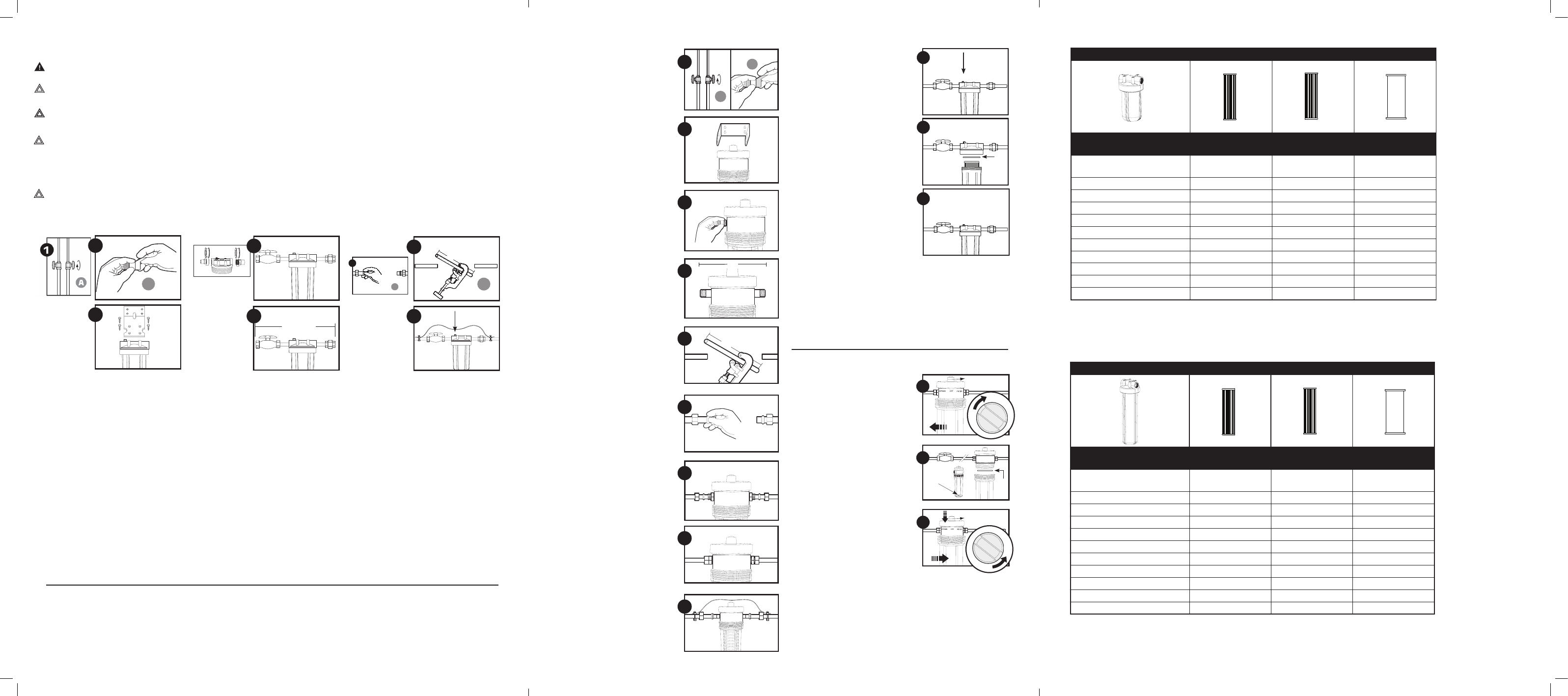
1.
Turn off water supply (
A
)and open
nearest faucet to drain pipes
before installation. Apply about 6
inches of Teflon
®
tape (
B
) in clock-
wise direction to pipe threads of
fittings.
2.
Use mounting bracket as a tem-
plate to mark screw locations.
Then place bracket over the cap
and align with inlet and outlet
ports.
IMPORTANT: Allow 1-1/2 inches
clearance below housing to enable
cartridge changes.
3.
Assemble all fittings. Fittings not
supplied. Use a wrench to tighten
firmly. DO NOT OVER-TIGHTEN.
About one thread should remain
visible.
4.
Measure length (shown as X
on diagram) across assembled
fittings and subtract 1 inch for
3/4-inch pipe or 1-1/2 inches for
1/2-inch pipe. Mark section of pipe
to be removed.
NOTE: Approximately 6 inches will
be removed for 3/4-inch pipe and
5-1/4 inches for 1/2-inch pipe.
5.
Using a pipe cutter or hacksaw,
cut and remove marked section of
pipe. File or sand sharp edges on
remaining pipe.
6.
Slip brass compression nut and
ferrule onto each end of pipe. If
installing on 1/2-inch pipe, substi-
tute rubber ferrule for brass ferrule.
7.
Align filter assembly with ends
of pipe, making certain the cap
opening marked “IN” is facing your
incoming water supply. It will be
necessary to spread ends of pipe
apart to install filter assembly.
Using two adjustable wrenches,
hold incoming fitting securely with
one wrench and tighten nut with
second wrench. Repeat process
for outgoing fitting.
8.
Turn on main water supply. Slowly
turn handle on housing 1/4-turn
counterclockwise to allow system
to fill with water. Check for leaks,
then rotate handle fully to “FILTER”
position. Open nearest faucet and
flush filter cartridge for 15 minutes.
9
.
CAUTION: If water pipes are used to
ground electrical systems, appliances or
phones, be certain to install a jumper wire.
Installation of Valve-in-Head (VIH) Housing
A. Turn water off by rotating handle on
top of housing in clockwise direction.
NOTE: This will shut off all water flow within
the household. Unscrew bottom of housing.
Discard used cartridge.
Rinse out housing and fill 1/3 with
water. Add 2 tablespoons of bleach
and scrub with nonabrasive brush or
sponge. Rinse thoroughly.
B. Remove O-ring from groove in hous-
ing and wipe O-ring and groove
clean. Lubricate O-ring with a coat-
ing of clean silicone grease Part#
92360. Insert O-ring back into groove
and smooth into place with finger.
NOTE: This step is important to ensure proper
housing seal. Make certain O-ring is seated
level in the groove.
Firmly insert new cartridge into hous-
ing. Make certain it slips over the
standpipe at the bottom of the hous-
ing.
C. Screw the bottom of housing onto
the cap until it is hand-tight. Do not
over-tighten. Slowly turn handle on
Cartridge Replacement
A
B
C
Open
abrir
cLOSe
cerrar
Turn on water supply slowly
to allow filter to fill with water.
Depress red pressure-relief button
to release trapped air. Check for
leaks before leaving installation.
NOTE: After installation, flush the cartridge
for 10 minutes, wait one hour, then flush
again for 10 minutes before using the water.
housing 1/4-turn counterclock-
wise to allow system to fill with
water.
Check for leaks, then rotate han-
dle fully to the “FILTER” position.
NOTE: Flush cartridge for 15 minutes
before use.
Installation of Standard Filter Housings
NOTE: Assembly of this filter Housing can be modified by
using various adapters. Fittings can be either sweated or
threaded.
• Please read all instructions, specifications, and precau-
tions before installing and using your water filter.
• Install filter cartridge in housing before proceeding
with installation (see Filter Cartridge Replacement VIH
Housing section).
• Install filter after water meter or pressure tank.
• Numbered diagrams correspond with numbered steps.
• See diagrams for corresponding steps. Only Teflon
®
tape
is recommended for fitting connections.
• Install after water meter or pressure tank.
Filter Cartridge Replacement of Valve-in-Head
(VIH) Filter HOUsing
Stand pipe
O-ring
BYpASS-water will bypass from the filter
OFF-shut the water off
FILter-In service
Operation, filtering
water
A
Cartridge Selection (For Filter Housing Model # H-PR-10BV-34 and H-PR-10BV-1)
Select the Cartridge Filter
for your water needs
PR-50-10BV
(Part# 26243)
PCP-5-10BV
(Part# 26178)
RF-10BV
(Part# 26255)
Filter Type
Pleated
Polyester Reusable
Pleated Cellulose
Cartridge - Polyester
Radial Flow Granular
Activated Carbon
Scale and Rust Particles
X
X
Coarse Sand
X
X
Sand/Dirt/Silt
X
Fine Dirt/Silt/Sand
X
Extra Fine Dirt/Silt/Sand
X
Bad Taste & Odor
X
Aethetic Chlorine: Taste & Odor
X
Filter Life (in months)*
6
6
6
Micron Rating (Nominal) +
50
5
Service Flow Rate gpm (lpm)**
10 (37)
10 (37)
2(7.4)
Cartridge Selection (For Filter Housing Model # H-PR-20BV-34, H-PR-20BV-1, H-20BV-15 & H-PR-20BV-15 )
Select the Cartridge Filter
for your water needs
PR-30-20BV
(Part# 26244)
PCP-5-20BV
(Part# 26180)
RF-20BV
(Part# 26256)
Filter Type
Pleated
Polyester Reusable
Pleated Cellulose
Cartridge - Polyester
Radial Flow Granular
Activated Carbon
Scale and Rust Particles
X
X
Coarse Sand
X
X
Sand/Dirt/Silt
X
Fine Dirt/Silt/Sand
X
Extra Fine Dirt/Silt/Sand
X
Bad Taste & Odor
X
Aethetic Chlorine: Taste & Odor
X
Filter Life (in months)*
6
6
6
Micron Rating (Nominal) +
30
5
Service Flow Rate gpm (lpm)**
20 (76)
20 (76)
4 (15)
*NOTE: Filter cartridge life varies depending on usage and water conditions
**NOTE: Flow rates measured at 60psi (4.1 bar)
The smaller the micron rating, the smaller the size particle the cartridge will filter. For comparison purposes, the human
hair has a diameter of approximately 70 microns. Particles smaller than 40 microns are not visible with the human eye
L
L
L
L