Hydrotech Aqua Flo Ultra 2 Under Sink Filter System User Manual
Page 4
Instruction #2 - Install Tubing to Quick Connect Fittings
PLASTIC TUBING
1. Cut tube ends square and straight.
Do not deform tube (i.e., cause tube
to compress its diameter so it is no
longer round).
2. Make sure outer surface of tube is
clear of marks or scratches for a
length equal to twice tube diameter.
This allows "O" ring to seat properly
against tube.
3. Avoid sharp changes in direction
when routing tubing. Sharp turns
cause tubing to flex and deform,
which reduces its flow capacity and
may increase lateral stress on the
fittings, causing leakage.
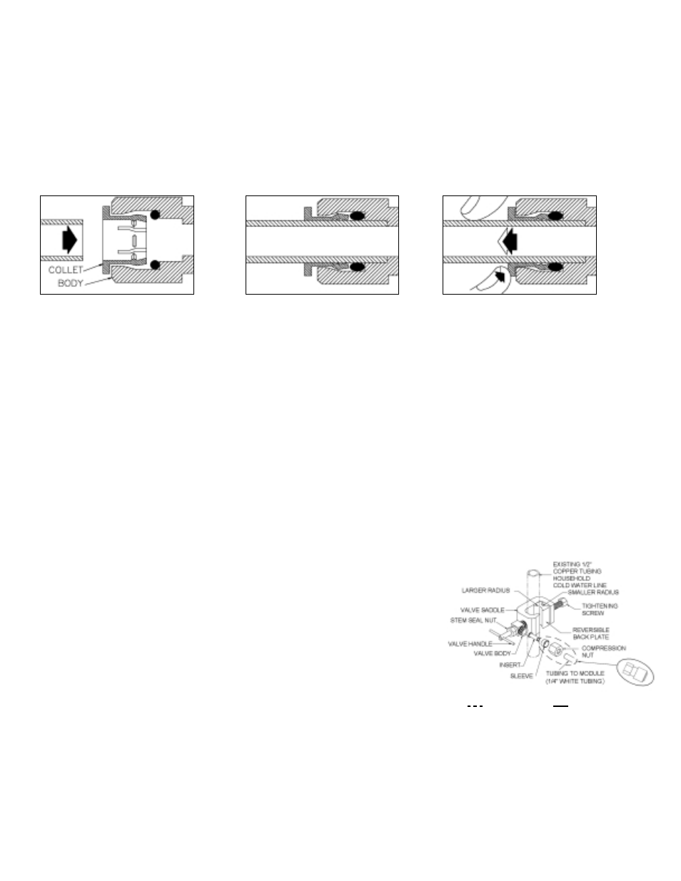
QUICK-CONNECT FITTINGS
Fittings consist of two parts: a Body and
a collet.
1. To install a tube, push it through
Collet until it seats firmly at bottom of
fitting (Figure A and B.).
2. To remove a tube, push and hold
Collet against Body while pulling tube
out (Figure C).
A. Push tube through Collet into Body.
B. Tube must seat firmly at bottom
of fitting.
C. Push Collet against Body to
release tube.
Instruction #3 - Saddle Tapping Valve Installation on Copper Tube
CAUTION: This saddle-tapping valve is
not designed for installation on flex line
tubing.
NOTE: State, provincial and local
plumbing codes may prohibit use of
saddle-tapping valves.
1. CAUTION: If no shut off valve is
installed under sink, close main water
valve during this Installation.
Locate shut off valves on water lines
under sink. To identify hot supply pipe
and cold supply pipe, turn both
faucets on and let water run. As water
flows, hot water pipe becomes
noticeably warmer.
2. CAUTION: Do not install feed water
assembly on hot water line.
Turn off cold water supply by closing
shut off valve. Drain line by opening
sink faucet. Some mixing type faucets
may require hot water supply be shut
off as well.
NOTE: All instructions refer to
components shown in Figure 1 unless
otherwise noted.
3. CAUTION: Do not turn valve handle
before or while installing saddle-
tapping valve. Make sure piercing
lance does not protrude beyond
rubber gasket before installing valve.
Assemble saddle-tapping valve
assembly on tube.
a.
Hold back plate against tube.
• 3/8" copper tubing use back
plate smaller radius.
• 1/2" copper tubing, use back
plate larger radius
b.
Hold valve saddle against tubing
in a position directly opposite
back plate.
c.
Tighten screw enough so valve
saddle and back plate are held
securely against tube.
d.
Rotate assembly so tubing
connection is aligned toward RO
Module feed port.
e.
Tighten screw firmly. Do not
crush tube.
4A. Connect source water feed tubing to
valve body using compression fitting.
a.
Slide nut and sleeve onto tubing
(in that order).
b.
Install insert into plastic tubing.
c.
Install tube with insert and
sleeve into valve body.
d.
Thread compression nut onto
valve body, tighten.
4B. Connect source water feed tubing to
valve body using connector.
a.
Apply NSF 61 grade Teflon tape
over the threads of valve body.
b.
Install the connector (Do not
overtighten)
c.
Firmly push the white tubing into
the quick connect fitting of
connector.
5. Turn saddle-tapping valve handle
clockwise until it is firmly seated and
piercing lance is fully extended.
6. CAUTION: Supply line is pierced and
valve is closed.
Do not open valve until system is
activated.
Turn on cold water supply. Check
saddle-tapping valve installation for
leaks. Allow water to run from faucet
for a few minutes to clear any debris
in the line caused by installation.
NOTE: If flow from sink faucet is
reduced, clean faucet aerator.
Figure 1: Saddle-Tapping Valve Assembly
P/N 92276 installed on 1/2”
Copper Tubing
7. Trim ¼” white tube to desired length.
Install ¼” white tube into ¼” white
collet as shown in Figure 1.
Compression
Nut Fitting
Connector