How your 9100sxt downflow water conditioner works, Performance, Control operation during regeneration – Hydrotech 9100 SXT Valve Meter Initiated Water Softener User Manual
Page 2
How Your 9100SXT Downflow Water Conditioner Works
Hard water enters your home through the main supply line, enters the softener and passes down through a resin mineral
bed which softens the water. An ion exchange process takes place in which the resin beads capture and hold calcium and
magnesium, the hardness minerals, while the water takes on sodium ions. The soft water then flows into your household
water line.
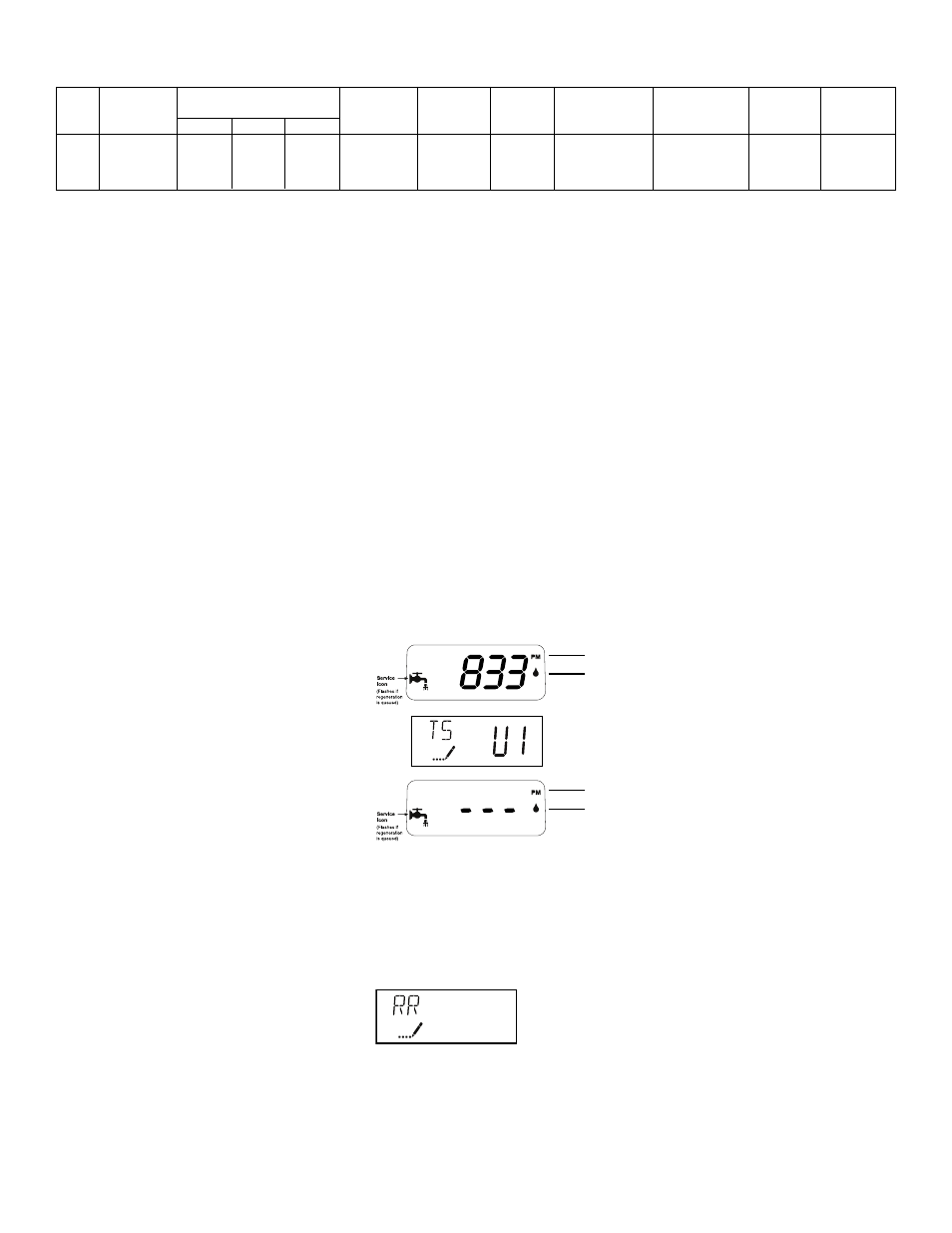
In normal operation, the Time of Day display will alternate being viewed with the Volume Remaining display then the Tank
in Service. This display will be in gallons, liters or cubic meters. The tank in service will be shown as U-I or U-2. As treated
water is used, the Volume Remaining display will count down from a maximum value to zero or (---).Once this occurs, a
regeneration cycle will be initiated at the Set Regeneration Time. Water flow through the valve is indicated by the Flow
Indicator that will flash in direct relationship to flow rate.
Example
833 Gallons of Treated
Water Remaining
Tank In Service
0 Gallons of Treated
Water Remaining
Control Operation During Regeneration
In regeneration, the control will display a special regeneration display. In this display, the control will show the current
regeneration step number the valve is advancing to or has reached and the time remaining in that step. The step
number displayed will flash until the valve has completed driving into this regeneration step position. Once all
regeneration steps have been completed, the valve will return to Service and resume normal operation.
Example
Less than 6 minutes
remaining in Regen
Step Rapid Rinse
Pushing the Extra Cycle Button during a regeneration cycle will immediately advance the valve to the next cycle step
position and resume normal step timing.
1
5
Performance
PM Indicator
Flow Indicator
(Flashing with water flow)
PM Indicator
Flow Indicator
(Flashing with water flow)
Item
Model
Capacity at regeneration salt levels
Service Flow
Maximum
Resin Volume
Mineral Tank Size
Brine Tank Size
Salt
Shipping
Number
Number
(kilograins as CaCO
3
)
Rate
(2)
Flow To Drain
per tank
Width x Height
Width x Height
Capacity
Weight
@15lb/cf
@10lb/cf
(1)
@6lb/cf
USGPM (LPM)
USGPM (LPM)
cu.ft. (litres)
inches (mm)
inches (mm)
Lbs. (kg)
Lbs. (kg)
7627
9100SXT-30 TMI
30
27
20
10 (37.9)
1.5 (5.7)
1.00 (28)
9 x 48 (229 x 1219)
21 x 36 (533 x 914)
308 (140)
185 (84)
7628
9100SXT-45 TMI
45
41
30
11 (41.6)
2.0 (7.6)
1.50 (43)
10 x 54 (254 x 1372)
21 x 36 (533 x 914)
308 (140)
248 (113)
7629
9100SXT-60 TMI
60
55
40
15 (56.8)
3.0 (11.4)
2.00 (57)
12 x 52 (305 x 1321)
21 x 36 (533 x 914)
308 (140)
340 (154)
(1)
10lb/cu.ft. salt dosage is the standard factory setting.
Operating Temperature Range: 34° to 110°F (1° to 43°C)
Operating Pressure Range: 20 to 120 psi (137 to 827 kPa)
Electrical: 24V/60Hz with a supplied 120V/60Hz Wall Mount Approved Class 2 Transformer
• Capacities are based on two tanks of resin. Eg: 9100SXT-30 set at 10lb/cf salt setting would provide
27,000 grains of hardness removal for one tank.
• These products are not intended to be used to treat water that is microbiologically unsafe or of
unknown quality without adequate disinfection before or after the system.
• The manufacturer reserves the right to make product improvements which deviate from the
specifications and descriptions stated herein without obligation to change previously manufactured
products or to note the change.
• Peak flow rates are intended for intermittent use only and are for residential application only.
• 1 kilograin is equal to 1000 grains.