Installation and start-up procedure, Installation instructions – Hydrotech 2510 Valve nextSand Turbidity & Sediment Filter Operation Manual User Manual
Page 3
2
Installation Instructions
CAUTION:
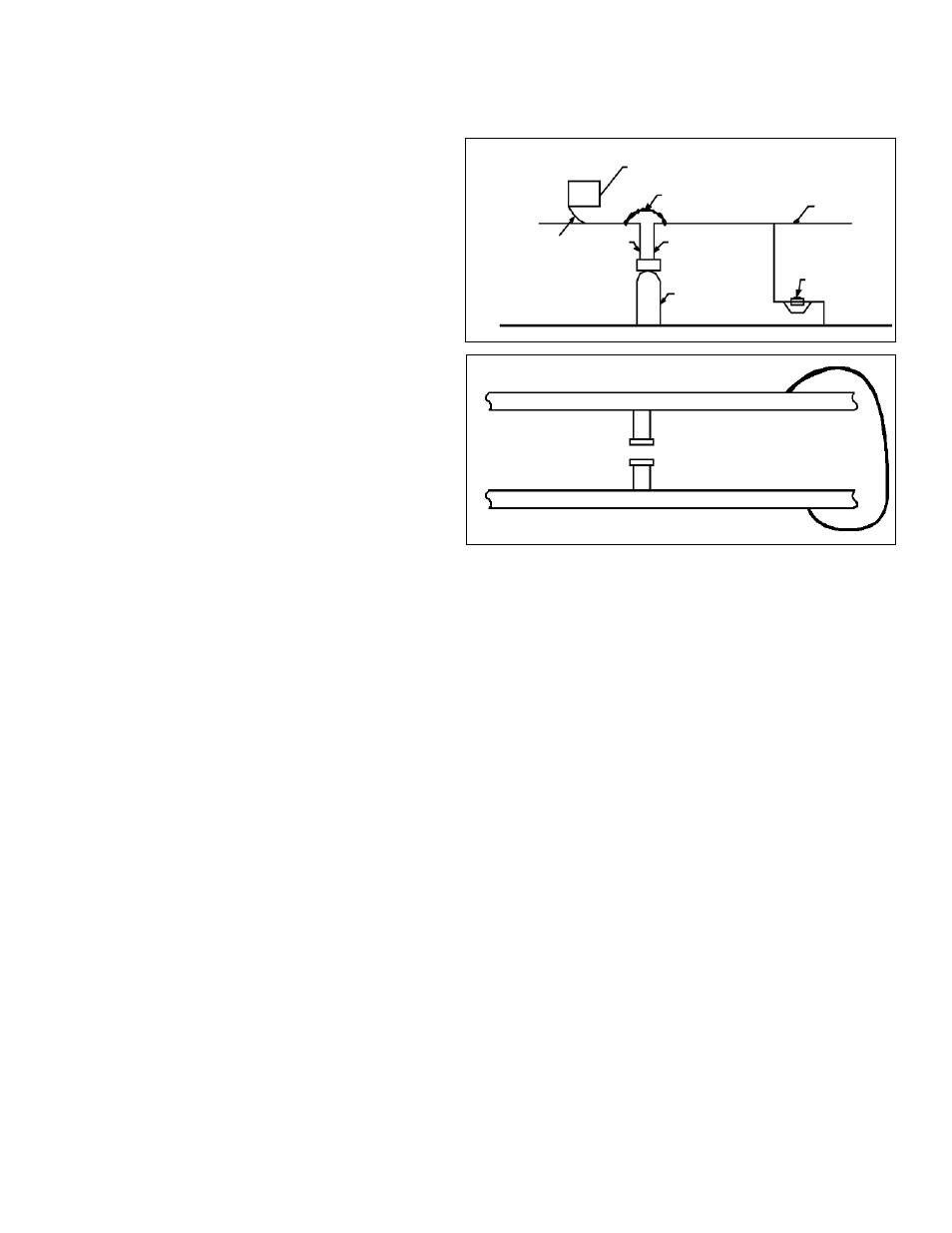
If the ground from the electrical panel or breaker box to the water
meter or underground copper pipe is tied to the copper water
lines and these lines are cut during installation of a Noryl bypass
valve and/or poly pipe, an approved grounding strap must
be used between the two lines that have been cut in order to
maintain continuity. The length of the grounding strap will depend
upon the number of units being installed and/or the amount of
copper pipe being replaced with poly. See Figure 1.
In all cases where metal pipe was originally used and is later
interrupted by poly pipe or the Noryl bypass valve as in Figure
1 or by physical separation as in Figure 2, to maintain proper
metallic pipe bonding, an approved ground clamp c/w not less
than #6 copper conductor must be used for continuity.
Check your local electrical code for the correct clamp and cable
size.
NOTE: This timer’s programs will be out of sync if you turn the
knob too far or do not allow the drive motor to stop completely
before continuing to the next step. If this happens while doing any
procedure, rotate the knob clockwise until the white dot lines up
with the time of day arrow and the unit will return to the service
position. You can then start again.
1. Place filter with chemical feeder container on a flat surface in desired location, near a drain and 115 volt AC outlet. Subjecting your
filter to freezing or to water temperatures above 120°F (49°C) will void the warranty. Remove the valve from the carton. Be sure the
distributor tube is in place. Carefully position the valve over it and turn securely on to the fiberglass tank.
Note: All multi media and some larger units are supplied with the media separate. Please refer to page 5 installations & Replacement
of Filter Media Pak.
2. Attach the installation kit or bypass to the control valve. Make inlet and outlet water connections to meet applicable plumbing codes.
A 3/4” inlet line is recommended. When sweat fittings are used, solder the adapters for the inlet and outlet to the copper pipe first.
This procedure is necessary because the controls must not be subjected to temperatures above 160°F (71°C). Then, using teflon
tape, screw the adapters for the inlet, outlet and drain into the valve. CAUTION: Do not use pipe thread compound as it may attack
the materials in the valve body.
3. On the drain, use the 1/2" hose barb supplied and a full 1/2" hose (not supplied) for the drain line and make the shortest run to a
suitable drain. The drain line must be secured in position at the end which discharges into the drain so it cannot be inadvertently
moved from the drain. An air gap may be required.
4. Loosen the two screws on the timer cover to remove it from the timer.
5. Automatic water filters are supplied from the factory in the backwash position, ready for start up. Turn on the water supply to the
unit. Open the supply line slowly and allow the air to escape from the filter before turning the supply water on all the way. Allow the
unit to backwash until all the air and media fines are no longer showing at the drain. This may take up to 15 minutes so you need
to unplug the timer until you are ready to continue.
6. Plug the timer in, set the time and frequency of regeneration following instruction on page 4. Allow the unit to complete the cycle on
its own from this point.
7. Make sure the bypass valve is in the service position.
ALL GOVERNMENT CODES GOVERNING INSTALLATIONS OF THESE DEVICES MUST BE OBSERVED.
Installation and Start-up Procedure
Electrical Panel
Ground Strap
Copper
Pipe
Filter
c/w Plastic
Bypass
Ground
From
Panel
Poly Pipe
Poly
Pipe
Water
Meter
Unfiltered Water Line for Outside & 3rd Tap Comes from Meter
Unfiltered Water Bypass
Loop Cut & Capped
Ground Strap Required
Because of break in continuity
Filtered Water Line in Home
Figure 1
Figure 2