Application troubleshooting, Automatic fill, Determining the settings of latch and invert – Flowline LC90 Remote Controller User Manual
Page 6: Automatic empty, Controller logic, Relay latch logic table
Step Eight
Step Nine
APPLICATION
TROUBLESHOOTING
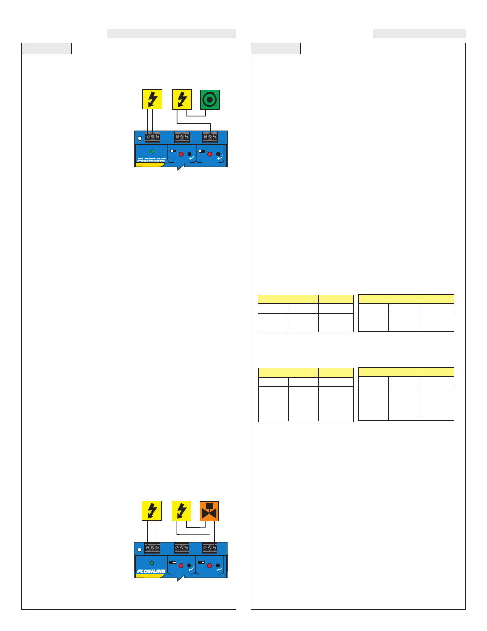
Automatic Fill
This system consists of a tank with a high level sensor, a low level
sensor, and a pump that is controlled by the controller. Part of a prop-
er fail-safe design for this particular
system is that if power is lost to the
controller for any reason, the pump
filling the tank must be turned off.
Therefore, we connect the pump to
the NO side of the relay. When the
relay is energized, the pump will
turn on and fill the tank. The relay
indicator will correspond directly
to the On/Off status of the pump.
Note:
If the pump motor load exceeds the rating of the controller’s
relay, a stepper relay of higher capacity must be used as part of the
system design.
Determining the settings of LATCH and INVERT
This is the way the system must operate:
•
When both the high and low sensors are dry, the pump should turn
on, starting to fill the tank.
•
When the low sensor gets wet, the pump should stay on.
•
When the high sensor gets wet, the pump should turn off.
Latch:
In any two-sensor control system, LATCH must be ON.
Invert:
Referring to the logic chart in Step Nine, we look for the set-
ting that will de-energize the relay (start the pump) when both inputs
are wet (Amber LEDs). In this system, Invert should be ON.
Determining A or B input connections:
When LATCH is ON,
there is no effective difference between Input A and B, since both sen-
sors must have the same signal in order for status to change. When
wiring any two-input relay section, the only consideration for hook-
ing a particular sensor to A or B is if LATCH will be OFF.
Automatic Empty
Note that a similar system logic can be used for an automatic empty
operation simply by controlling a pump that pumps fluid out of the
tank instead of into it. However, note the importance of fail-safe
design. If the tank is being passively filled, and a pump must be used
to actively empty it, a power failure to either the controller or the
pump circuits will cause overflow.
Alternatively, an electrically-controlled drain valve could be used. In
this case, the valve should be a type that will automatically open if
power is lost; in other words, power must be used to hold it closed.
The valve would be connected to the NO side of the relay—if power
is lost to the controller, the relay de-energizes, the valve loses the
power that was holding it shut, and fluid will drain from the tank into
some other safe containment until power is restored. In this system,
whenever the red relay LED of the controller is ON, the drain is
closed, allowing fluid to rise.
In this case, Invert should be On:
when both sensors are wet, the relay
de-energizes, the switch to the valve
opens, and the tank will drain. When
both sensors are dry, the relay
energizes, the switch to the valve
closes and the tank stops drain-
ing.
Controller Logic
For all controllers, please use the following guide to understand the
operation of the FLOWLINE LC90/LC91/LC92 controllers.
1. Make sure the Green power LED is On when power is supplied to
the controller.
2. The input LED's on the controllers will be Amber when the switch
is wet and Green when the switch is dry. Note: see Section 5
regarding reed switches. If the LED's are not switching the input
LED, test the level switch.
3. When the input LED's turn off and on, the relay LED will also
switch. With invert Off, the relay LED will be On when the input
LED is On and Off when the input LED is Off. With invert On,
the relay LED will be Off when the input LED is On and On when
the input LED is Off.
4. LC91 and LC92 model only: When both inputs are wet (amber
LED's On), the relay will be energized (red LED On). After that,
if one switch becomes dry, the relay will remain energized. Only
when both switches are dry (both amber LED's Off) will the con-
troller de-energize the relay. The relay will not energize again
until both switches are wet. See the Logic Chart below for further
explanation.
Relay Latch Logic Table:
Relay 2 can either be a independent relay similar to relay 1 or can be
a latching relay with latch ON. With Latch Off, relay 2 will only
respond to the INPUT 2A setting. INPUT 2B will be ignored.
With Latch ON, relay 2 will actuate when INPUT 2A and INPUT 2B are
in the same condition. The relay will not change its condition until both
inputs reverse their state.
Caution:
Some sensors (particularly buoyancy sensors) may have
their own inverting capability (wired NO or NC). This will change the
logic of the invert switch. Check your system design.
Invert OFF
Latch OFF
INPUT 2A*
ON
OFF
INPUT 2B*
No Effect
No Effect
Relay
ON
OFF
Invert ON
Latch Off
INPUT 2A*
ON
OFF
INPUT 2B*
No Effect
No Effect
Relay
OFF
ON
Invert OFF
Latch ON
INPUT 2A*
ON
OFF
ON
OFF
INPUT 2B*
ON
ON
OFF
OFF
Relay
ON
No Change
No Change
OFF
Invert ON
Latch ON
INPUT 2A*
ON
OFF
ON
OFF
INPUT 2B*
ON
ON
OFF
OFF
Relay
OFF
No Change
No Change
ON
R E L A Y 1
R E L A Y 2
P O W E R
- +
- +
I N V E R T
D E L A Y
I N V E R T
D E L A Y
R E L A Y 1
R E L A Y 2
P O W E R
- +
- +
I N V E R T
D E L A Y
I N V E R T
D E L A Y