Warning, Caution – EBARA EFQT-2 User Manual
Page 13
EBARA Fluid Handling 12
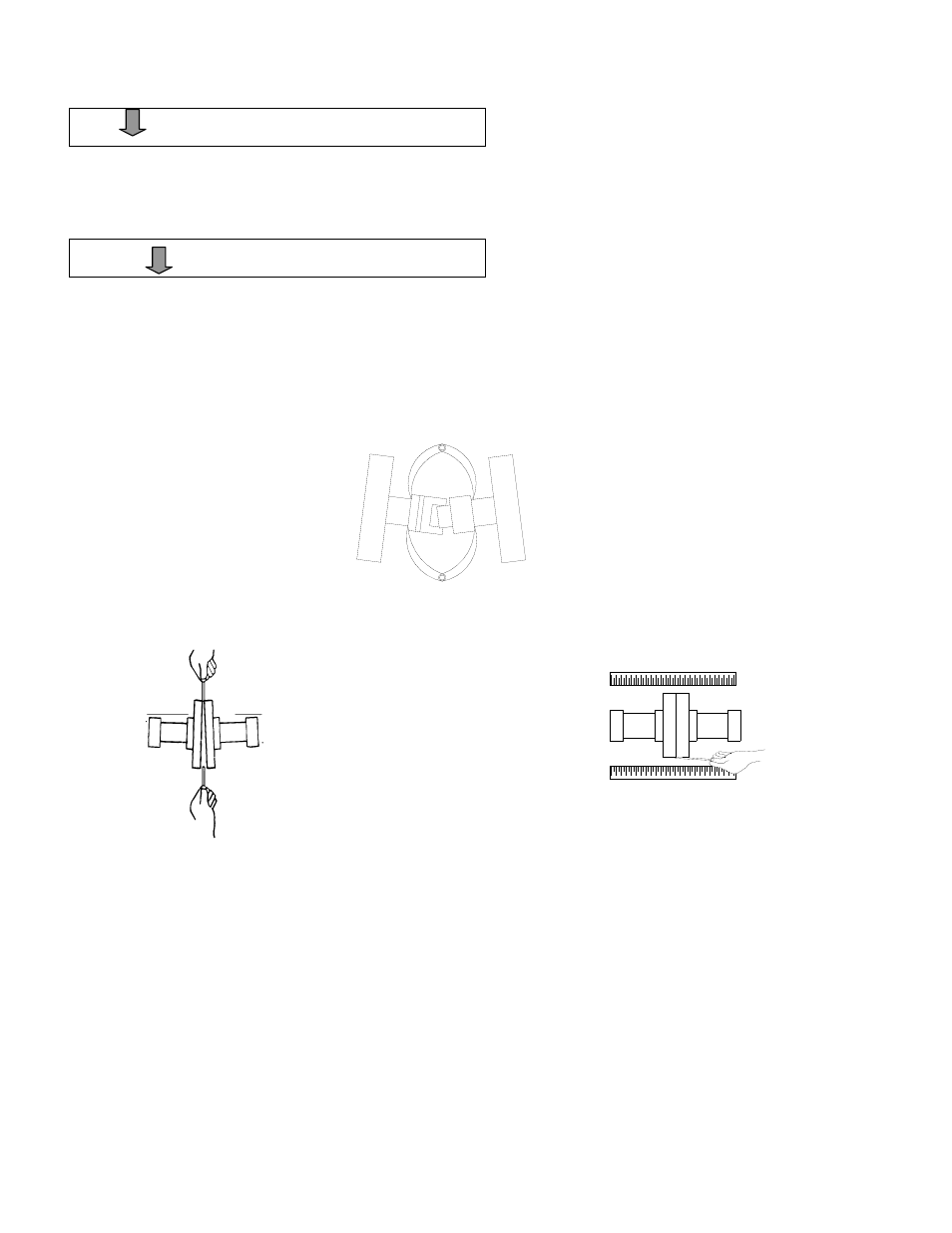
Figure 6A. Aligning Spider – Type Couplings
F
Figure 6B. Aligning Non-Spider Type Couplings
WARNING!
When checking alignment, disconnect the power source
to ensure that the pump will remain inoperative.
CAUTION!
Adjusting the alignment in one direction may alter the
alignment in another direction. Check each procedure
after altering alignment.
Coupled Drives
When using couplings, the axis of the power
source must be aligned the axis of the pump shaft
in both the horizontal and vertical planes. Most
couplings require a specific gap or clearance
between the driving and the driven shafts. Refer to
the coupling manufacturer’s service literature.
Align spider insert type couplings by using calipers
to measure the dimensions on the circumference
of the outer ends of the coupling hub every 90
degrees. The coupling is in alignment when the
hub ends are the same distance apart at all points
(see Figure 6A).
Align non-spider type couplings by using a feeler
gauge or taper gauge between the couplings halves
every 90 degrees. The coupling is in alignment when
the hubs are the same distance apart at all points
(see Figure 6B).
Check parallel adjustment by laying a straightedge
across both coupling rims at the top, bottom, and
side. When the straightedge rests evenly on both
halves of the coupling, the coupling is in horizontal
parallel alignment. If the coupling is misaligned use a
feeler gauge between the coupling and the
straightedge to measure the amount of misalignment.
V-Belt Drives
When using V-belt drives, the power source and
the pump must be parallel. Use a straightedge
along the sides of the pulleys to ensure that the
pulleys are properly aligned (see Figure 6C). In
drive systems using two pr more belts, make
certain that the belts are a matched set;
unmatched sets will cause accelerated belt
wear.