Cable gland assy diag 1, Declaration of conformity, Diag 2 adaptor assy – Delta Controls 310 User Manual
Page 2
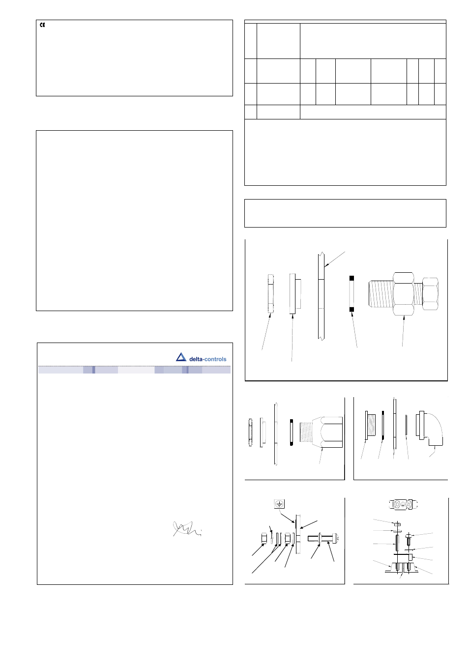
WIRING
Cable Glands and adaptors – The enclosure is supplied with a through hole of 22 mm
blanked with a blind grommet. Discard the grommet and fit a suitable proprietary brass or
nylon M20 cable gland with thread length of 10 mm and locknut. Fit the nylon reducer
provided to the inside and a fibre washer to the outside. See diagram 1.
Alternately, the enclosure may be supplied from the factory with a threaded adaptor ready
to accept the customer’s gland or conduit system.
Alternatives:
i)
a metal or nylon adaptor may be used to accommodate other sizes of gland eg
NPT, or conduit system. See diagram 2.
ii)
an elbow kit may be supplied to enable the entry to be rotated axially through
90° and radially through 360°. See diagram 3.
Earthing / grounding – The user must make suitable local earthing arrangements, if
required, to ensure that metal glands are earthed.
An earthing point is provided inside the enclosure. If this is disturbed in any way it must
be reassembled correctly to be an effective earth and retain ingress protection. See
diagram 4. When removing the lid slacken the M4 nut first and ensure it is re tightened
whenever the lid is replaced. See diagram 4.1.
EARTHING / GROUNDING OF PROCESS CONNECTION AND MOUNTING
BRACKETS – All the internal dead metal work is bonded to the enclosure earthing point.
Due to requirements of sealing, the process connection and mounting brackets may be
isolated from the earthing point. Do not, therefore, rely on either for earthing, instead
always use the earthing point provided. If required, the process connection and mounting
brackets may be bonded locally. Never use the process connection or inlet pipe for
locally grounding welding equipment unless it is separately earth bonded.
Pollution degree – all products are suitable for use in pollution degree 3.
Electrical isolation – These products are not suitable for electrical isolation. Always isolate
circuit separately to carry out any electrical work.
T A B L E A – M I C R O S W I T C H R A T I N G S
S
W
I
T
C
H
C
O
D
E
U L / C S A
M I C R O S W I T C H
I E C 9 4 7 - 5 - 1 / E N 6 0 9 4 7 - 5 - 1 R A T I N G
R A T I N G
( R E S I S T I V E )
U
i
m
p
U
i
D e s i g n a t i o n
&
U t i l i s a t i o n
Category
V A
* S E E N O T E
R A T I N G
( I e I U e )
M
a
k
e
B
r
e
a
k
5 A @ 1 1 0 / 2 5 0
V A C
0 . 6 / 0 . 3 A @
1 2 0 / 2 4 0 V A C
A C 1 4 / D 3 0 0
A
C
4 3 2
7 2
0 0
0 . 8 k
V
2 5 0 V
0 . 2 2 / 0 . 1 A @
1 2 5 / 2 5 0 V D C
D C 1 3 / R 3 0 0
D C
2 8
2 8
5 A @ 1 1 0 / 2 5 0
V A C
0 . 6 / 0 . 3 A @
1 2 0 / 2 4 0 V A C
A C 1 4 / D 3 0 0
A C
4 3 2
7 2
0 2
0 . 8 k
V
2 5 0 V
2 A @ 3 0 V D C
0 . 2 2 / 0 . 1 A @
1 2 5 / 2 5 0 V D C
D C 1 3 / R 3 0 0
D C
2 8
2 8
1 A @ 1 2 5 V A C
0 4
1 A @ 1 2 5 V A C R E S I S T I V E ( I E C 1 0 5 8 - 1 / E N 6 1 0 5 8 - 1 )
* 1 0 0 m A @ 3 0
V D C
T h e e l e c t r i c a l r a t i n g i s d e p e n d e n t o n t h e m i c r o s w i t c h f i t t e d t o t h e
i n s t r u m e n t . T h e e l e c t r i c a l r a t i n g i s d e f i n e d b y e a c h a p p r o v a l
t h a t t h e m i c r o s w i t c h c o m p l i e s w i t h a n d i s s h o w n o n t h e p r o d u c t
n a m e p l a t e , i e U L / C S A , o r I E C . I t s h o u l d b e n o t e d t h a t t h e
s w i t c h m u s t b e u s e d w i t h i n t h e e l e c t r i c a l r a t i n g s p e c i f i e d f r o m
t h e a p p r o v a l y o u r e q u i r e . T a b l e A l i s t s t h e a c t u a l I E C r a t i n g s
a g a i n s t t h e D e s i g n a t i o n & U t i l i s a t i o n C a t e g o r y m a r k e d o n t h e
n a m e p l a t e . I n t h e a b s e n c e o f a n y v e r i f i c a t i o n b y U L / C S A t h e
m i c r o s w i t c h * m a n u f a c t u r e r ’ s r a t i n g i s s p e c i f i e d i n b o l d i t a l i c s .
I f i n d o u b t , s e e k g u i d a n c e f r o m f a c t o r y .
ENCLOSURE WALL
LOCKNUT
NYLON 22/20
REDUCER
FIBRE WASHER
PROPRIETARY
GLAND
CABLE GLAND ASSY
DIAG 1
CABLE GLAND /
CONDUIT ADAPTOR
DIAG 2
ADAPTOR ASSY
GLAND
SCREW
FIBRE
WASHER
O RING
SEAL
½" NPT Pg 13.5
M20 X 1.5 ¾ ET
ENCLOSURE
WALL
DIAG 3
ELBOW ASSY
EARTH LABEL
ENCLOSURE WALL
(EXTERIOR)
SCREW
BONDED SEAL
SINGLE
COIL
WASHER
PLAIN
WASHERS
STAR WASHER
NUT
NUT
DIAG 4
EARTHING ASSY
M4 PLAIN
WASHER
M4 SCREW
EARTH
STRAP
M4 STUD
M4 SINGLE
COIL WASHER
M4 NUT
LID
BASE
GASKET
DIAG 4.1
EARTH STRAP
Declaration of Conformity
We: Delta Controls Ltd
Island Farm Avenue
West Molesey
Surrey, UK
KT8 2UZ
As the manufacturers of the apparatus listed, declare under our sole responsibility that the products listed
below:
Pressure, Pressure Difference, Temperature & Flow switches series “W” or “A”:
201, 202, 203, 281, 204, 207, 208, 209, 231, 232, 233, 234, S21, S22, S24, GR2, GR4, VM2, VM4.
301, 303, 304, 381, 384, 306, 386, 310, 316, S31, S34, GR3, GR6.
721, 731, 771, 722, 732, 772, 723, 733, 773, 781, 734, 774, 741, 742, 743, 744, S71, GR7.
131.
To which this declaration relates are in conformity with the following relevant standards or parts thereof:
EN 60947-1 :1992
Low voltage switch gear and control-gear-general rules.
EN 60947-5-1:1992
Low voltage switch gear and control-gear-control circuit devices and switching
elements.
EN 60529: 1991 Specification for classification of degrees of protection provided by enclosures.
EN 60950:1992 Safety of information technology equipment including electrical business equipment:
section 2.5.
BS 6134:1991
Specification for pressure and vacuum switches.
And thereby conforms to the requirements of the Low Voltage Directive 73/23/EC amended by 93/68/EEC.
Signed:
………………….
R. Harrison
Managing Director
Original dated 22
nd
June 2000
Rev. B dated 12
th
August 2009
Low Voltage Directive (LVD) – 2006/95/AC. Switch products with enclosure codes
‘W’ and ‘A’ supplied CE-marked must be installed and used in accordance with the
main instructions and this addendum supplied with each product. Products rated
lower than 50V ac and 75 V dc are outside the scope of the LVD, and therefore, do
not require CE-marking under this directive. The LVD does not apply to products
with enclosure codes ‘H’, ‘K’, ‘R’, ‘M’, ‘N’ for use in hazardous areas. Switch products
with enclosure codes ‘H’, ‘K’, ‘R’, ‘M’, ‘N’, are covered by the Explosive Atmospheres
Directive ATEX – 94/9/EC and when CE-marked will indicate compliance with this
directive alone. The following directives do not apply to switch products
manufactured by Delta Controls:
Electromagnetic Compatibility EMC – 2004/108/EC
Machinery Safety Directive MSD – 2006/42/EC