Fig 6, Fig 7, Fig 8 – Delta Controls GR3_6 User Manual
Page 2: Fig 11, Fig 13, Declaration of conformity
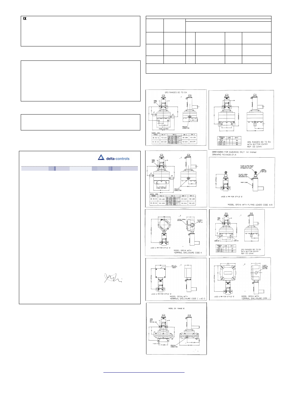
TABLE A – MICROSWITCH RATINGS
SWITCH
CODE
(type)
UL/CSA
MICROSWITCH
RATING (Resistive)
*See Note
IEC 947-5-1/EN 60947-5-1 RATING
Designation
& Utilization
Category
VA
Uimp
Ui
RATING
(Ie/Ue)
MAKE
BREAK
HS, HD, HR
11A @ 110/250 VAC
0.8kV
250V
0.6/0.3A @
120/240 VAC
AC14/D300
AC
432
72
5/0.5 @ 30/125 VDC
0.22/0.1A @
125/250VDC
DC13/R300
DC
28
28
HP, HQ, HT
5A @ 250 VAC
0.5kV
250V
0.6/0.3A @
120/240 VAC
AC14/D300
AC
432
72
2A @ 30 VDC
0.22/0.1A @
125/250VDC
DC13/R300
DC
28
28
HV, HW, HY
1A @ 125 VAC
0.5kV
120V
0.3A @ 120 VAC
AC14/E150
AC
216
36
*1A @ 30 VDC
The electrical rating is dependent on the microswitch fitted to the switch. The electrical rating is defined by each approval that the
microswitch complies with and is shown on the product nameplate, ie UL/CSA or IEC. It should be noted that the switch must be
used within the electrical rating specified from the approval you require. Table A lists the actual IEC ratings against the Designation
and Utilisation Category marked on the nameplate. If in doubt, seek guidance from factory.
Low Voltage Directive (LVD) – 2006/95/AC. Products with enclosure codes ‘W’ and ‘A’ supplied CE-
marked must be installed and used in accordance with the main instructions and this addendum supplied
with each product. Products rated lower than 50V ac and 75 V dc are outside the scope of the LVD. The
LVD does not apply to products with enclosure codes ‘H’ and ‘R’, for use in hazardous areas. Such
products are covered by the Explosive Atmospheres Directive ATEX – 94/9/EC and when CE-marked will
indicate compliance with this directive alone. The following directives do not apply to switch products
manufactured by Delta Controls:
Electromagnetic Compatibility EMC – 2004/08/EC.
Machinery Safety Directive MSD – 2006/42/EC.
WIRING
Junction box cable glands and adaptors. Optional Junction box code ‘C’ is supplied with an M20 x 1.5
tapped hole blanked with a red plug. Discard the red plug and fit a suitable proprietary brass or nylon M20
cable gland with thread length of 10 mm. Fit a fibre washer to the outside. See diagram 1.
Alternately the junction box may be supplied from the factory with a threaded adaptor ready to accept the
customer’s gland or conduit system.
Alternatives:
1) a metal or nylon adaptor may be used to accommodate other sizes of gland eg NPT, or conduit system.
See diagram 2.
Earthing / grounding – Use earthing point provided inside the junction box (when fitted). The user must
make suitable local earthing arrangement, if required, to ensure that metal glands / adaptors are earthed.
Pollution degree – all products are suitable for use in pollution degree 3.Ref EN60947-5-1
Electrical Isolation – these products are not suitable for electrical isolation. Always isolate circuit
separately to carry out any electrical work.
Fig 5
Fig 6
Fig 7
Fig 8
Fig 9
Fig 10
Fig 11
Fig 12
Fig 13
In the interest of development and improvement Delta Controls Ltd, reserve the right to amend without notice,
details contained in this publication. No legal liability will be accepted by Delta Controls Ltd, for any errors,
omissions or amendments.
YOUR TRUSTED PARTNER IN PROCESS INSTRUMENTATION
DELTA CONTROLS LIMITED, ISLAND FARM AVENUE, WEST MOLESEY, SURREY KT8 2UZ
T
+44 (0) 208 939 3511
F
+44 (0) 208 783 1163
E
W
www.delta-controls.com
Stock No: 002522/GR3
Registered Office Registered in England No 5369683
Declaration of Conformity
We: Delta Controls Ltd
Island Farm Avenue
West Molesey
Surrey, UK
KT8 2UZ
As the manufacturers of the apparatus listed, declare under our sole responsibility that the products
listed below:
Pressure, Pressure Difference, Temperature & Flow switches series “W” or “A”:
201, 202, 203, 281, 204, 207, 208, 209, 231, 232, 233, 234, S21, S22, S24, GR2, GR4, VM2, VM4.
301, 303, 304, 381, 384, 306, 386, 310, 316, S31, S34, GR3, GR6.
721, 731, 771, 722, 732, 772, 723, 733, 773, 781, 734, 774, 741, 742, 743, 744, S71, GR7.
131.
To which this declaration relates are in conformity with the following relevant standards or parts
thereof:
EN 60947-1 :1992
Low voltage switch gear and control-gear-general rules.
EN 60947-5-1:1992
Low voltage switch gear and control-gear-control circuit devices and switching
elements.
EN 60529: 1991 Specification for classification of degrees of protection provided by enclosures.
EN 60950:1992 Safety of information technology equipment including electrical business equipment:
section 2.5.
BS 6134:1991
Specification for pressure and vacuum switches.
And thereby conforms to the requirements of the Low Voltage Directive 73/23/EC amended by
93/68/EEC.
Signed:
………………….
R. Harrison
Managing Director
Original dated 22
nd
June 2000
Rev. B dated 12
th
August 2009